
The Vanwall Grand Prix engines
Part 1: The 2-litre F2 engine
Author
- Ron Rex
Date
- January 8, 2020
Related articles
- The Vanwall Grand Prix engines, by Ron Rex
- Introduction
- Part 2: The 2.3-litre interim F1 engine
- Part 3: Technical anomalies
- Part 4: The 2.5-litre F1 engine
- Part 5: The 'AvGas' 2.5-litre F1 engine
- Part 6: The 2.6-litre Intercontinental Formula engine
- Part 7: Finality and overview
- Part 8: Specifications and other facts
- Vanwall - The Green Comet: the brief history of the Vanwall, by Don Capps
- Vanwall - Vanwall's inconspicuous entry to the GP world, by Felix Muelas/Don Capps
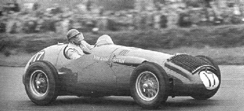
Who?Alan Brown What?Vanwall Special Where?Silverstone When?1954 International Trophy (May 15, 1957) |
 |
Why?
The first Vanwall engine was a 4-cylinder inline DOHC water-cooled motor with a bore and stroke matching the 1952 works Norton 500 (498.74cc) on which it was modelled, viz.85.93 x 86 mm, giving a swept volume of 1,995 cc (the official statement on the cars competition debut gave a swept volume of 1998 cc, but it calculates to 1,994.98cc). Ever since the experimental water-cooled BRM/Norton of 1949, which had the bore & stroke of the then works 500 single (82.2 x 94 mm), Norton's Joe Craig had been steadily increasing the bore and reducing the stroke of the works 500 GP engine in his search for more power.
Note
In 1957, Eric Richter wrote an article on racing engine design published in The Autocar magazine in which he revealed details of his preliminary investigations into the design of the Vanwall engine. He stated that two of the limiting factors in engine design were max. mean piston speed and max. piston acceleration and that at the time (1952-53) the limits were considered to be 4000 ft/min and 100,000 ft/sec2 respectively. These limits were both reached at 7,200rpm with a stroke of 3.350, almost identical to that adopted for the Vanwall engine (86mm-3.383) and of the works Norton 500 single on which it was based and the stated speed of 7,200rpm, was virtually where these two engines developed their max. power.
The Vanwall engine had a deep crankcase into which the 4-cylinder barrels were spigoted and these were topped by a shallow cylinder head casting. All these components were tied firmly together, by 10 long threaded high-tensile steel rods, that passed through the head, beside the cylinder barrels, and through the crankcase and main bearing caps and were secured at each end with nuts (refer to the crankcase description for specific detail relating to this first engine).
When the B40 crankcase was ordered for study, contact was also made with Leyland Motors who were making the engine under contract for Rolls-Royce and the Government, requesting the supply of a set of patterns and baked cores for suitable modification. Vandervell's connections with the motor industry were proving very helpful.
The RR B40 was a F-head engine (overhead inlet-side exhaust) with a cast iron block/crankcase and an aluminium head and was used mainly in the Austin Champ military vehicle. It had a bore & stroke of 88.9mm x 114.3mm for a swept vol. of 2838cc and the cylinder centre spacing was 105.4mm. It also had a 5 main bearing crankshaft.
1.1 Crankcase
The team at Acton first set about modifying the B40 crankcase/block they had acquired. They machined away the cylinder block portion effectively leaving just the crankcase. This removed the exhaust ports and exhaust valve housings of the F-head configuration, but much more work was required to adapt the crankcase for its use in the proposed racing engine, particularly as the camshaft tunnel of the B40 was located within the remaining crankcase that was to be used as a base.
So Vandervell Products used the machined B40 crankcase as a pattern, together with the cores supplied by Leyland Motors, to cast a prototype crankcase in aluminium alloy for the 2-litre Vanwall. But considerably more modification was needed by VP, both to increase the wall thickness to allow for the reduced strength of the alloy to be used and to incorporate the other modifications wanted by Richter. Prime among these was the decision by Fox and Richter to modify it to accept a 4 main bearing crankshaft, by removing the centre main bearing support. New wooden patterns and cores incorporating these changes had to be made by VP, before a satisfactory casting could be made of the definitive crankcase to be used. By mid-1952, the casting was ordered from Aeroplane and Motor Aluminium Castings Ltd. of Coventry in RR53B aluminium alloy.
With the source B40 engine having 5 main bearings, this was a significant change to specify only 4 main bearings for the Vanwall engine. Presumably, Fox and Richter thought it was warranted, by the savings in friction and weight. It is interesting that previously Richter had worked alongside the very experienced engineer Stewart Tresilian at ERA and BRM and Tresilian strongly championed the use of four main bearings in 4-cylinder racing engines, as evident in his design for the 2.5-litre P25 BRM 4-cylinder GP engine finalised in 1953 and raced during the 1954-60 Formula 1 series.
The final Vanwall crankcase was a very rigid structure, with walls extending 65mm below the crankshaft centre line and over 25mm thick at the top where they supported the cylinder barrels. It was closed by a finned light alloy sump, which was quite deep for a dry sump. On this first engine with no centre main bearing, presumably the two middle tie rods that clamped the components together, were shorter and clamped up against the roof of the crankcase chamber. There were two tall breather pipes bolted to the left side of the crankcase chamber wall and on each corner of the crankcase, small cast engine mounts were bolted on. The bell-housing was a separate casting.
1.2 Crankshaft
The Vanwall had a forged crankshaft based on the RR B40 one, using the same 69.9mm (2.75) diameter main bearing journal and 50.8mm (2.0) diameter crankpin journal, all of considerable width; but there was one significant difference. As Richter had decided on a 4 main bearing crank, the B40 crankshaft design was changed, by deleting the centre main bearing and incorporating a counterbalanced flying middle throw instead. Counterbalance weights were also used on webs nos. 2 & 7. The webs were 20mm thick and the throw was adjusted to 43mm to give a stroke of 86mm. The main bearing caps were very deep and sturdy.
Naturally, Vandervell Thin Wall bearings were fitted, copper-lead-indium ones.
By mid-1952, Smith's Stamping Works of Coventry were given an order to forge the crankshafts in 1% chrome molybdenum EN19 steel and then they were sent to Laystall Engineering in Wolverhampton for machining and balancing. Surface treatment of the bearing faces was carried out by VP.Smiths Stampings, comprised the Coventry works & Smith-Clayton Forge Ltd in Lincoln who would forge the later crankshafts.
1.3 Cylinders and Reciprocating Components
The 4 wet cylinder barrels were spigoted for a distance of 55mm (one third of their length) into the top of the crankcase and into the cylinder head at their other end. They were a major part of the engines strong structure and were manufactured in DTD 485 spec cast-iron, by Wellworthy Ltd of Lymington. They were surrounded by a contoured water jacket, cast in RR50 aluminium alloy by Aeroplane and Motors Aluminium Castings, that slipped down around the cylinders and curved behind the tie bolts which held the engine together. This was in effect an open jacket, that was lightly clamped between the cylinder head and crankcase. It had flanges top and bottom that located over the tie bolts and provided seats to seal on rubber gaskets. Water manifolds were attached to each side of the water jacket, fed cooling water from the dual outlets of the water pump mounted at the front of the engine.
The slipper type pistons (with skirts cutaway on the non-thrust bearing sides) were as used in the works Norton 500 and were forged in RR59 aluminium alloy by High Duty Alloys. The final machining of the piston blanks was done by Hepworth and Grandage. There were three piston rings, the top two being Dykes L-section compression ones, the third an oil control ring. The piston crown had valve clearance recesses and was shaped to provide squish areas with the combustion chamber at the top of its travel. Norton's Leo Kuzmicki had first incorporated squish areas into their racing singles in 1951, to increase turbulence and improve combustion with very positive results and this concept was carried over to the Vanwall engine.
The connecting rods were I section, 163.5mm long centre/centre, forged from EN24 nickel steel by Smith Clayton Forge. They were machined all over to give a web thickness of 2.54mm and then polished. The big-end was split horizontally and the cap was secured by two bolts, while the little-end articulated on a short 25mm diam. gudgeon pin retained in the piston by circlips. The flanks of the connecting rod merged tangentially with the gudgeon pin end.
1.4 Cylinder Head & Valve Gear
The Vanwall cylinder head was in effect four of the latest works Norton 500 heads, incorporated in a common water-cooled casting. Vandervell's team of designers liaised closely with Norton's Craig and Kuzmicki, obtaining parts for study and referring the VP design drawings to them for scrutiny. The Norton combustion chamber, ports and valve sizes were faithfully copied. In plan the four inlet ports were angled to the rear, at 75o to the engine centreline to promote axial swirl in the hemispherical shaped combustion chambers, to improve burning. This reflected existing Norton practice, adopted after consultation with Harry Weslake, the engine gas flow expert. The inlet and exhaust valves were inclined symmetrically at a valve included angle of 64°, as in the works Norton of the time (the experimental BRM/Norton single of 1949 had a VIA of 77°). The inlet ports were 44.5mm in dia. and the exhaust ports 39.4mm in dia.
The outer part of each of the four cast inlet ports protruded some distance from the bulk of the head casting (reducing charge heating) with a slight downdraft angle of 20° to the horizontal, resulting in a total flow angle to the cylinder axis in the transverse plane of 70°. The inner curve of the inlet port at its junction with the valve seat was not parallel to the valve axis but was angled at 20° to it, insufficient with the VIA of 64° to create any barrel turbulence, as was later exploited by Keith Ducksworth in the design of Cosworth's FVA & DFV engines.
The head was cast in RR50 aluminium alloy by Aeroplane and Motor Aluminium Castings and incorporated annular recesses in the edge of the combustion chambers into which the cylinder barrels were spigoted. Around these were lands that clamped circular Wills pressure ring copper gaskets against a flange on each barrel, to secure the fire-joints (these were to prove problematic until a fix in 1956). The head casting had thin walls to get maximum volume for cooling water and there were inserted stellited bronze-alloy valve seats, while the combustion chambers and ports were fully machined. The outer edge of the cylinder head extended down to seal with the water jacket around the cylinder barrels, via an interposed rubber gasket.
Twin spark plugs per cylinder, angled to be normal to the combustion chamber surface, were incorporated along the engine centreline (the Norton single cylinder 500 had only one spark plug).
There were four water off-takes in the head, above each of the cylinders between the spark plugs, but offset to the exhaust side and to which a water manifold was connected by short rubber hoses.
The exhaust valves were made from austenitic steel containing 0.48% carbon, 13.02% chromium and 2.14% tungsten and were hollowed out from the head end and sodium filled to aid cooling. The heads were sealed by discs welded onto them. The exhaust valve guides were finned and in direct contact with the cooling water for much of their length. Both sets of valve stems protruded well out of the top of the cylinder head and each valve stem, was surrounded by dual hairpin valve springs which were angled off the line of the camshafts, to provide space for the valve springs of the cylinder next in-line.
The cylinder head was quite shallow, as the camshafts were carried in separate housings mounted on steel pedestals 40mm clear of the head. This left an open space which was occupied by the valve stems and valve springs. There were eight flanged pedestals supporting each housing, positioned either side of the hairpin springs and parallel to the valve stems and this gave the cylinder head quite a spiky appearance. This open air mounting allowed access to secure the nuts on the tie rods holding the engine together and room for twin spark plugs per cylinder, that wouldnt have been possible if the springs were enclosed by the casting. But this meant that the shallow cylinder head had less beam strength (even with the bolted on housings) than if it was deeper and had included them.
The camshaft housings were open top magnesium alloy boxes capped by flat plates secured by a multiplicity of cap screws. The camshafts ran in five plain bearings with separate bearing caps and were rifle-bored by B.S.A. The cams had a small base circle radius and as a consequence had considerable lobes and reflected Kuzmicki's expertise in this area of design.
There were short cylindrical tappets located within the camshaft housings, interposed between the cams and the valve stems and sliding in bronze guides. The tappets were hollowed out, closed at the valve end by a screwed in head. The camshaft end was radiused and rotation of the tappet was prevented by a flat machined on one side, that abutted against a keeper plate. Valve clearance was set by varying the head thickness of caps fitted over the ends of the valve stems.
Oil was fed to the cam boxes by external lines, with drain pipes returning it to the sump. Seepage down the cylindrical tappets was controlled by the precision fit of the tappets in their guides, a tribute to the quality of VP machining, as seepage was minimal.
The camshafts were driven off the crankshaft by a train of spur gears (turning on Italian R.I.V. ball bearings) contained in a separate oil tight magnesium alloy casting bolted to the front of the engine. Initially a chain drive had been considered, but it did not proceed beyond the drawing board stage. A second smaller gear case was attached to front of this primary one, drive coming from an extension of the shaft of the second idler gear in the camshaft drive. This outer case provided bevel gear drives for the magnetos and a drive for the fuel pump.
1.5 Carburation
The engine was fitted with four motor-cycle type, Amal 3GP carburettors with remote float chambers .The size used has never been publicly documented, but the largest GP carburettor listed by Amal in a July 1956 brochure, had a throat diam. of 49.2mm (1 15/16) and this is likely what was fitted. There is comment on one of the motor-cycle enthusiasts websites that the Vanwall had specially made 2 (50.8mm) Amals.
The Amal GP type carburettor had a side mounted mixture needle, outside of the throttle bore and together with its unique slide barrel throttle, gave a totally unobstructed air passage at full throttle.
Air intake trumpets with large radii bell mouths were fitted to each carburettor.
The carburettors were operated by wire pull cables, two for each instrument; one for the slide throttle and the other for the side mixture strength needle. There was a horizontal shaft mounted on top of the inlet cam box, on which a series of paired large and small radii quadrant pulleys were attached (eight in total) and each throttle cable was connected to a large quadrant and each needle cable to the adjoining small one. The accelerator pedal worked a bell crank and pull-rod, that rotated the quadrant throttle shaft to operate the carburettors.
The carburettors were fed fuel from two remote mounted float chambers which in turn were supplied fuel under pressure from a Ceco fuel pump that was mounted low down on the left side of the crankcase and driven by a V-belt from a pulley fixed to the end of the spindle shaft of a gear that was driven off the magneto drive shaft and positioned below it (in the supplementary gear case on the front of the engine).
The float chambers were hung on spindles from rubber mounting plates attached to small diameter tubular support frames which were welded to the top chassis rail, each float chamber feeding two carburettors. One float chamber was located near the front of the engine, the other near the rear.
This form of mounting was necessary to try and isolate the float chambers from the secondary vibrations inherent in a large 4-cylinder in-line engine. Initially Amal float chambers were fitted but they suffered fuel frothing from the vibrations and after a series of trails, S.U. float chambers were adopted as they functioned better.
But carburettors were only an interim measure, as Vandervell intended to fit a form of Bosch fuel injection. It is testimony to Vandervell's high standing in the automotive industry, that although there was an exclusive contract between Bosch and Daimler Benz for the use of Bosch's fuel injection system, both were to agree to VP's request to also use it. However Bosch were to decline a similar request from Maserati in 1954. The fact that VP supplied Thin Wall bearings for Mercedes Benz vehicles undoubtedly had some bearing on the two German companies agreement to Vandervell's use.
1.6 Exhaust System
Norton used tuned lengths of inlet and exhaust pipes, to make use of resonant pressure pulses in them, to enhance gas flow and with Craig and Kuzmicki's help, this was incorporated in the design of the Vanwall engine.
Initially four separate exhaust pipes were fitted with lengths of 29 (73.7cm). The pipes exited the side of the bodywork and were arranged horizontally along the side of the car one on top of the other, in the order of (from the top) cylinders 1, 4, 2 and 3, with a deflector plate protecting the bodywork at the pipe ends .This was the exhaust system used when the car was first run at RAF Odiham airfield in early 1954.
Megaphone exhausts as used on the Norton 500 had been tried but were found to make no significant difference.
When the car made its first race appearance in May 1954, the exhaust system had been modified by the fitting of a 4 into 2 into 1 collector onto the ends of the four separate pipes, from which a single exhaust pipe extended to the back of the car, over the top of the rear suspension. The primary pipes from cylinders 1 & 4 and from cylinders 2 & 3 were joined together and then merged into one by the collector.
1.7 Ignition System
The Vanwall had two 14mm spark plugs per cylinder and magneto ignition. In May 1952, VP placed an order with British Thomson-Houston Co., Ltd. (B.T.H.) for the supply of a special 4-cylinder magneto to fire two plugs per cylinder at up to 8,000rpm. B.T.H. developed a rotating magnet/stationary winding magneto, as then used in aircraft engines. It had a four lobe cam with a double-ended rotor and development was quite protracted. Experiments were conducted with the timing of the two sparks in each cylinder, by staggering them by several degrees. But it was concluded that the sparks should occur simultaneously for best combustion and to achieve this, a special form of dual secondary winding was developed and adopted for the Vanwall magneto.
All this took time and the B.T.H. magneto was not ready to fit to the 2-litre engine on its race debut in May 1954. As an interim measure, the engine was fitted with twin Scintilla magnetos which were mounted horizontally opposite one another, across the front of the timing cases; each firing one plug per cylinder. These magnetos were each driven by bevel gears from the take-off shaft that extended from the primary cam timing case into the secondary gear drive case. K.L.G. spark plugs were used.
1.8 Lubrication System
The Vanwall had a dry-sump lubrication system with gear-type oil pumps. There was a triple pinioned scavenge pump and a single pressure pump housed in a casting fixed to the front of the engine below the crankshaft. Drive to these, came from a second gear on the crankshaft (behind the camshaft drive) which drove a gear shaft that powered the oil pumps; the pressure pump in front (and also driving the water pump in front of that) and the scavenge pump at the back. Oil pressure was 60psi to the mains (with a 15psi feed to the rear mounted gearbox) fed through an oil filter located to the right side of the engine and a special mixture of SAE 50 & SAE 20 castor-based oil was used, supplied by Shell Mex & BP.
The dual entry scavenge pump drew oil from two screened pick-ups at the front and back of the sump which had a transverse baffle in the middle and was finned. There was a long cylindrical object mounted on the top chassis rail alongside the exhaust cam box and it was connected to the cooling system and header tank and it is speculated, that this was an oil-water heat exchanger, as the enclosed nose (see part 1.9) would have precluded the use of a conventional oil radiator. Marston Excelsior Ltd. had supplied VP with Integron tubing for oil cooling and it is further speculated that this tubing was used to convey the oil through the oil-water heat exchanger (Integron tubes, are tubes with fine low finning where the fins are spirally extruded from a thick walled tube). This exchanger was used up till at least the Goodwood meeting in September 1954 (as is evident from photos), even though by then the car had been fitted with a conventional water radiator and an open nose. The oil tank was located beside the engine, under the carburettors, with its filler cap recessed into the bodywork.
1.9 Cooling System
The engine's cooling was critical, as there was not a lot of metal in the shallow cylinder head. A water pump was mounted low down at the front, driven by the same shaft as the oil pumps. It had two outlets which fed cooling water to each side of the water jacket around the cylinders. Heated water was drawn off the cylinder head, above each combustion chamber by rubber hoses and fed into a manifold, connecting to the water radiator and a scuttle mounted header tank.
On the first car, a special gilled tube surface radiator made from Clayton-Still Wire-Wound tubing was mounted flat on top of the sloping enclosed nose of the car. The idea behind this was to remove hot air from the engine compartment which could adversely affect engine power. A very large and accurate water temperature gauge was fitted in the dashboard to help the driver monitor the engine temperature.
1.10 Race Performance and Development 2-Litre 1954
Development of the 2-litre F2 engine took longer than anticipated and it became clear that the car would not be finished in time to compete in the F2 championship races of 1953. There was always an intention to develop a 2.5-litre engine to compete in the new F1 in 1954, but now plans were advanced to hasten the work on it.
By the end of 1952, Harry Begg, one of VP's technical directors was in Stuttgart discussing fuel injection with Daimler Benz and Robert Bosch GmbH as was then being developed by them for Mercedes Benz's future production 300SL and forthcoming F1 car. Vandervell's intention was to try and incorporate it into the 2-litre engine but this proved to be too ambitious and it would be early 1955 before it was adapted to the 2.5-litre Vanwall engine.
In February 1953, Norton Motors was absorbed by Associated Motorcycles Ltd. and the Vandervell family sold out their interest in Norton, although Tony Vandervell continued his close association with Craig, Smith and Kuzmicki and the rest of the racing team on the design of the Vanwall engine.
Development of the 2-litre and design of the 2-5 litre engines proceeded throughout 1953 and by December the first 2-litre engine ran on the Maidenhead test beds. It was run initially for just three minutes at 1,500rpm and development and testing continued so that in January 1954 it had produced 148bhp at 5,150rpm.
By the 3rd of March 1954, Vandervell wrote to Kuzmicki reporting that the engine was now developing 235bhp at 7,500-7,600rpm using straight exhaust pipes 29 long and that it was taken up to 7,800rpm without problems (this corresponds to a bmep of 204-201 psi). This was a very high peak power bmep and a high specific output of 117.5bhp/litre, much more than its contemporaries, but as the 1953 Works Norton 500 was giving 54bhp at 7,200rpm on petrol (108bhp/litre), this statement of the Vanwall's power on alcohol-based fuel could possibly be creditable.
But then DSJ who had access to Factory records wrote in Motor Sport magazine of March 1974 that the engine was developed to an output of 180bhp but he didn't say when. Certainly it would have developed at least 220bhp based on the Norton power output.
Vandervell approached his fuel suppliers Shell-Mex and BP Ltd. who started to develop more potent methanol-based fuels in the quest for more power.
The engine was started by a portable electric motor with a long driveshaft that was inserted through a tube in the nose of the car and engaged with the end of the crankshaft.
There was a scoop in the bonnet feeding air to the carburettors but it just fed into the engine bay in the vicinity of the carburettors and wasn't sealed around them.
The engine was installed in the first car, named the Vanwall Special (Vanwall was a contraction of Vandervell and Thin Wall) and an entry was made for the Easter Goodwood meeting on 19 April, but the entry had to be withdrawn as the nominated driver, Ascari, could not attend. Testing of the car continued at RAF Odiham airfield. The car's tubular chassis was made by Cooper Cars (T30) with Ferrari-derived suspension and steering components. A Ferrari 4-speed gearbox/final drive modified by VP was utilised, the Goodyear disc brakes as used on the Thin Wall Special were also fitted. The bodywork was smooth with a fully enclosed nose.
The first public appearance was at the International Trophy race at Silverstone on 15 May 1954 with Alan Brown driving. Brown was very impressed with the car, finding the engine very smooth and observers commented on how relatively quiet the exhaust note was compared to other 4-cylinder racing engines and on the car's high rate of acceleration out of corners, reflecting good mid-range torque. A unique feature was that it was possible to see the exposed valve springs working away, when the engine was running with the bonnet off.
Brown set 5th fastest time in first practice, 3 seconds faster than the other 2-litre cars. Second practice was wet and the Vanwall was fastest, so it started Heat 1 of the race on the front row and went on to finish sixth, ahead of all the other 2-litre cars. In the final the Vanwall got as high as fifth place before retiring on lap 17 with a broken oil pipe. Nevertheless, a promising start.
At this meeting, the cooling system was upgraded, the car was fitted with a cowl over the original tube water radiator and a second tubed surface radiator was placed on top of the cowling, effectively doubling the surface area and it was reported that two S.U. float chambers were fitted to supply the carburettors.
Following the race, the 2-litre engine was removed and taken to Maidenhead for further development and it completed over 20 hours running on the test beds without problems .But it never raced again, as it subsequently destroyed itself during further endurance testing.
After the car's first appearance, VP were offered free use of Super Metalflex stainless steel flexible piping and fittings by Power Flexible Tubing Co. Ltd of London and in 1955 they were adopted for all of the car's external oil lines.