
The Gurney-Weslake 3-litre V12 Grand Prix engine
Author
- Ron Rex
Date
- October 16, 2020
Related articles
- Dan Gurney - All-American Racer, by Mattijs Diepraam
Who?Dan Gurney What?Eagle-Weslake T1G Where?Monte Carlo When?25e Grand Prix Automobile de Monaco (May 7, 1967) |
 |
Why?
In 1966, when the new Grand Prix formula for 3-litre un-supercharged or 1.5-litre supercharged cars came into effect, engine designers turned to many different types of engine configuration and cylinder head layout in their endeavours to produce competitive Formula 1 engines for the new formula. One engine stood out for its advanced concept in cylinder head design, featuring four valves per cylinder at a narrow valve-included angle of 30° in a shallow pent-roof combustion chamber atop oversquare-dimensioned cylinders with flat top pistons. That engine was the 3-litre Gurney-Weslake Type 58 V12 designed and built by Weslake & Company Ltd. in England to power Dan Gurney's All American Racers, Eagle Formula 1 car.
This concept in engine design gave a considerable improvement in terms of volumetric and thermal efficiencies over contemporary practice (and came from research into high speed combustion carried out for Shell by Weslake). It combined the benefits of four valves per cylinder, (more valve area and lower valve mass) with a compact, efficient combustion chamber that allowed high compression ratios and shorter strokes, for gains in engine speed and power. The concept would go on (with the subsequent innovation by Keith Duckworth of Cosworth Engineering of an inlet throat angle to create 'barrel turbulence' in the cylinder) to be adopted as the standard for all Grand Prix engines (and ultimately most production engines) to the present day.
1 - Overview of the evolution of cylinder-head configurations
None of the touted features found in the Gurney-Weslake V12 were new, they had each appeared previously in Grand Prix engines, but this was the first time they were all incorporated into one design in their most effective combination and it pioneered the modern narrow valve-included angle (VIA) four-valve concept.
Four valves per cylinder had been used from early times but because of the small-bore, long-stroke engines then in vogue, the valves were generally set at a VIA of around 60° in pent-roofed combustion chambers that were often diametrically bigger than the cylinder bore so to provide room for valves of sufficient size, but this compromised the combustion-chamber shape.
In the 1920s the simpler concept of two valves per cylinder in hemispherical combustion chambers also gained considerable favour but with VIAs of as much as 100° which required pistons with domed crowns to produce even the low-compression ratios the engines then operated with, and wasn't ideal. Four valves per cylinder were still utilised, most notably by Daimler-Benz.
Post-World War II, two valves per cylinder at VIAs of generally 60-80° were the preferred choice and as engines became more oversquare to limit piston speed as peak-power revs rose, pistons needed more steeply domed crowns to achieve the higher compression ratios now possible as better and more potent fuels were used. The resultant combustion chamber at Top Dead Centre was shaped like an 'orange peel', far from efficient, and many engines used two spark plugs per cylinder to ignite the mixture. Racing engine manufacturers did experiment again with four valves per cylinder but generally found no significant improvement because they retained the wide VIAs favoured at the time, which again compromised combustion chamber shape.
In 1966 three other engines appeared with four valves per cylinder but they retained wide VIAs:
- - The Coventry Climax 2-litre FWMV MkX V8 with a VIA of 60° used by Lotus in the interim
- - A 3-litre version of the DOHC Ford Indy V8 with downdraft inlets and a VIA of 72° used by Mclaren
- - The Honda RA273E V12 with downdraft inlets and a VIA of 75°
The time was rife for an advance in combustion-chamber layout to fully exploit the potential advantages of four valves per cylinder and the Gurney-Weslake Type 58 V12 debuting at the Italian GP in September did just that. The epoch-making Ford Cosworth DFV V8 with virtually the same cylinder-head configuration but with the addition of 'barrel turbulence' would make its appearance at the Dutch GP in June of the next year.
2 - All American Racers Inc,
All American Racers Inc. (AAR) was founded late in 1964 by Daniel Gurney and Carroll Shelby with substantial backing from the Goodyear Tyre and Rubber Company to build cars to compete in the United States Auto Club (USAC) Championship races and Formula 1 Grand Prix racing. The company would produce Gurney's own cars called Eagles.
For some time Gurney had harboured the desire to race an American-built car in international events and had discussed the idea with like-minded fellow American Carroll Shelby back in late 1962, but nothing came of it at the time. Gurney went on with his successful career racing for the Porsche works team and then in 1963 he moved to the Brabham team (having previously raced for Ferrari and BRM) and while at Brabham had set up a small team in California (Dan Gurney Racing) to compete in American races. Earlier, in 1962, Gurney had encouraged Colin Chapman of Lotus to enter cars in the Indianapolis 500 race and subsequently he drove there for Lotus in 1963 and 1964; it was a series of events at the 1964 race that created an opportunity for Gurney to pursue his dream of racing an American-built car on the world stage. That year, all of the Goodyear-shod entries changed over to Firestone tyres for the race and Goodyear vowed to break Firestone's monopoly of wins at the Indy 500 by funding a team they would have more control of. They first approached Shelby for help, but he was fully committed to his own projects and suggested Gurney was the one to do it, given Gurney's experience racing for Lotus at Indy. Goodyear met with Gurney and agreed to give him substantial funding to set up a team with the prime goal to win at Indianapolis, though Gurney negotiated agreement for the team to also compete in Formula 1. Gurney was to be responsible for setting up facilities, assembling the workforce and hiring designers and the general running of the team; for his part, Shelby was granted a half share in the company and would act as both consultant and adviser.
A site for the team's base was acquired on South Broadway in Santa Ana south of Los Angeles, California, where a purpose-built facility complete with engine test cells was erected. It was fitted out with all the necessary equipment and machinery and was ready for occupation by September 1965. The cars were to be designed, built and operated out of these works and Gurney set about hiring experienced staff to achieve just that, key among these were talented craftsman Pete Wilkins, engine builder John Miller, machinist Jerry Whitfill, mechanics Bill Fowler and Ken Deringer (from his earlier team) and Bill Dunne who would be the Formula 1 team manager.
Gurney would leave the Brabham team at the end of 1965 to concentrate entirely on his own team. Although cars to race at Indy were first priority, the Formula 1 car project was also started as it was to be designed for the new 3-litre formula starting in 1966 and it was to be powered by a V12 engine designed and built by Harry Weslake's company in Rye, England.
3 - Weslake & Company Ltd.
Harry Weslake was a specialist in engine gas flow and combustion chamber design and had a research establishment, Weslake & Company Ltd., that was located in Rye, Sussex on the South East coast of England. The facility included five engine test cells, and Weslake had developed the technique of measuring air flow through valves and ports and the degree of turbulence in combustion chambers to very good effect.
He first used the technique of checking airflow in engines in 1923, after observing the tests done on coin-in the slot gas meters which monitored the amount of gas the meters flowed from a miniature gasometer of known volume. He modified the equipment so that it reversed the flow to suck air through a test piece and recorded the time taken to pass the known volume of air through it. Over the years this process was refined and in 1939 when the capacity of the gasometer proved inadequate for experimental work, he developed another device that allowed continuous airflow testing, consisting of an electrically driven blower discharging air through an orifice flowmeter which also allowed turbulence tests with swirl spinners in the combustion chambers of cylinder heads.
With this experience and expertise, Weslake did consultancy work for many British car manufacturers and had worked on increasing the performance of the racing engines from Norton, Jaguar, Connaught, Vanwall, BRM, Coventry Climax and many others.
The head of BRM, Sir Alfred Owen, valued the work Weslake had done for them, and in September 1962 purchased a 20% shareholding in Weslake & Company Ltd. He then appointed his former chief designer, Peter Berthon, to set up a BRM 'Advanced Projects' R&D office at Weslake & Company Ltd. at Rye. Berthon was made a director and was joined by Aubrey Woods from BRM who was to be chief designer. Weslake let them have a small workshop where they installed modern dynamometers and started recruiting staff to work on projects. However, prior to this in July 1962, BRM chief designer Tony Rudd had approached the Shell Group for help in investigating varying power outputs in their 1.5-litre V8 Grand Prix engines and Shell agreed to help. Later that month, Dr. Geoff Harrow from the Shell Research Laboratories at Thornton arrived at BRM to commence investigations and tests which were completed by late August. Harrow discovered combustion and mixture problems and suggested changes which resulted in the engines giving more power and with consistency. Shell was so impressed with what they had learnt that early in September, they approached Rudd with a proposal for a contract to carry out further high-speed combustion research using resources at BRM. But Berthon got wind of the proposal and insisted that as this was research, it should be done at Weslake & Company, and Sir Alfred agreed. So the Shell contract went to Rye and it commenced with Berthon initiating the design of a high-speed research engine, which would become known as the Shell Twin.
4 - The Shell Twin research project
The contract with Shell ran for two years and required Weslake & Company to design and commission a twin-cylinder high-speed engine to research and develop the combustion of fuel at high engine revolutions and to investigate new concepts in engine design that could advance this.
Berthon sought someone to manage the Shell project and over May and June of 1963 interviewed Roy Franklin, an ex-Rolls Royce Motors engineer, for the job. At these meetings, Berthon described that his concept for the task was an engine with four valves per cylinder set vertically in-line with the cylinder axis in a bathtub combustion chamber. In a letter of 23rd July, Berthon confirmed that Franklin had been appointed as project manager and that he could start on the 26th August. But when Franklin started at Weslake & Company, he found that Berthon had left and set up his own independent design office.
Nevertheless, Franklin was briefed by Weslake to begin by evaluating the four-valve bathtub concept that Berthon had originally put forward. Weslake made available his airflow measurement facilities and helped in the comparison of data obtained with that of other contemporary engines while Aubrey Woods provided help obtaining performance information and components from BRM. Woods would also detail the crankcase drawings and associated components of the test engine.
Berthon's four-vertical-valve concept was modelled in a block of softwood (attached to a wooden cylinder) and then tested for airflow, which proved very positive with breathing significantly better than current racing engine practice. It was clear that higher engine speeds of up to 13,000rpm could be achieved without the engine running out of breath and subject to dynamic stresses being contained, 15,000rpm was possible. The team then set about detailing the design of the cylinder head but it soon became apparent that with four vertical valves of sufficient size to flow the volume of air needed for the speeds envisaged, there would be insufficient space to accommodate a spark plug in the ideal location (the centre of the bathtub combustion chamber) because of a lack of clearance with the valve springs and valve gear.
So Franklin detailed a new model with the inlet and exhaust valves splayed slightly apart, which then made space for a centrally placed spark plug in what was now a shallow pent-roof-shaped combustion chamber which still had the same significant improvement in airflow as in the first concept. He determined that a VIA of 30° was the minimum needed to accommodate the revised layout, but settled on a small increase to a VIA of 32° (with the valves symmetrically inclined), as this would allow the gear drive to the camshafts to mate with the existing gear drive on the BRM 1.5-litre V8 Grand Prix engine, should BRM choose to adopt it. The shape of ports that produced the best gas flows was determined following tests done on re-worked versions of the wooden model cylinder head; the rate of swirl in the cylinder was also tested.
What was also improved was combustion because of the much better shaped combustion chamber now possible as the piston could be virtually flat-topped and still achieve an effective high compression ratio; it no longer needed to be highly domed as was the case with current wide-angle valve layouts which compromised the chamber shape.
4.1 - The Shell Twin engine in detail
It was decided that the research engine would be constructed as a parallel twin-cylinder unit to allow more scope for in-cylinder testing and it was given the Weslake project number of WRP22. The cylinder proportions were largely governed by the use of parts accessed from BRM via Berthon's earlier ties and Woods' contacts there. Cylinder liners, connecting rods, piston rings and head sealing gaskets were available from BRM which set the bore at 68.5mm while the same stroke as the BRM engine of 50.8mm was adopted, which gave a single-cylinder capacity of 187.5cc for a total swept volume of 375cc. The BRM pistons could not be used because of their high-domed crowns, and bespoke forged pistons were considered too expensive at this stage of the project, so as a first step cast pistons were obtained from Hepworth & Grandage, which being not as strong as forged ones, unfortunately limited engine speed to 13,000rpm.
Design was commenced in August 1963 and Franklin detailed the cylinder head to be cast in RR50 aluminium alloy with the first design drawing completed on the 2nd December 1963, while Woods did the cylinder block, crankcase and crankshaft and through his engineering contacts procured many components for the engine. Weslake's step-son Michael Daniel (technical director of the company) had returned from America and set up a machine shop to make the key components of the engine in-house to maintain secrecy on the project. He also went about setting up their own pattern-making shop and casting foundry, but these weren't established when the first castings were required for the Twin, so Franklin organised for the cylinder heads to be cast by a small firm run by Mike Allen in Ashford Kent. The engine was constructed so that different stroke/bore ratios and connecting rod lengths could be evaluated by changing components of its structure.
The engine had a DOHC driven by a Uniroyal-toothed rubber belt, with the valves actuated by bucket tappets and closed by coil springs. The inlet ports for each cylinder exited the head separately and had a steep downdraft angle of 42° to the horizontal so that the total inlet flow angle to the cylinder axis was 48° in the transverse plane. The inlet valves initially had a head diameter of 27.94mm, but with development this was increased to 29.2mm. The lift was 7.62mm in both cases. The inlet valve head area to piston area ratio was 0.363 for the larger valve size.
The exhaust ports from each cylinder merged into one oval-shaped port at the head face and were upswept at an angle of 25° to the horizontal. Both the ports and the exhaust valve guides were surrounded by the water jacket to aid cooling. The exhaust valves had a head diameter of 23.19mm and the lift was 6.35mm.
4.2 - The Shell Twin engine development
The 375cc engine was first fired up on test on the 11th June 1964 and development started. Barely two weeks later on the 23rd June, the engine was run at 11,000rpm, initial power was 37.5 bhp. Then on the 29th August 1964 it was run for 30 minutes at 11,000-12,000rpm.
Tests were then made using both Amal carburettors (2 x 1 15/16") on a manifold and fuel injection into each of the four inlet trumpets that were fitted to the valve ports.
Power curves were then taken on the 9th November 1964, recorded on 'test sheet 64' which showed:
| Inlet valve head dia. 27.94mm | Compression ratio of 11.68:1 |
- - Max. power - carburettors : 51.5bhp @ 9,800rpm
- - Max. power - fuel injection : 54.5bhp @ 10,200rpm - with readings taken up to 11,300rpm
- - Max. BMEP - 188psi @ 7,400rpm for both setups but with fuel injection holding 186psi @ 10,000rpm
- - The torque curve of the injected engine was particularly flat from 7,400rpm to 10,200rpm
Development continued determining key aspects of the concept and by December 1964, improvements to airflow gave 4.8% more power at higher rpm.
The project was publically announced in an article published in the 20th of January 1965 issue of Motor Cycle News.
A power curve dated 8th April 1965 of the 375cc engine, following further development and fitted with separate exhaust pipes with megaphones (and a compression ratio of 11.33:1 and the 29.2mm inlet valves) showed:
- - Max. power of 59.8bhp @ 12,600rpm with a very flat torque curve from 7,000-12,500rpm
- - The BMEP peaked at 170psi @ 7,000rpm and 172psi @ 10,000rpm
This meant that peak torque was effectively developed at only 55.5% of peak power rpm and then remained almost constant. It was a very flexible engine developing almost 160 bhp/litre, with potential for further development for higher power outputs given the relatively low peak BMEP pressures developed, although that would be at some loss to the useable power band.
Then in May 1965, Weslake was tasked by Sir Alfred Owen of BRM to investigate the potential of a four-valve per-cylinder V12 for BRM's use in the new 3-litre GP formula starting in 1966, while BRM itself evaluated an alternative two-valve-per-cylinder H16 concept. For his part, Weslake diverted resources to produce a 500cc version of the 375cc Shell Twin so that research could be carried out that was specifically applicable to a proposed 3-litre V12 GP engine. As the Shell contract was nearly at the end of its two-year term, no further development was done on the 375cc Twin.
As things transpired, BRM chose to proceed with their H16 concept and Weslake's work on a V12 would find use from another quarter.
Cross-section of the Shell Twin Research Engine
4.3 - The 500cc Weslake Twin
The 500cc twin cylinder was just an enlarged version of the 375cc Shell Twin, with the bore and stroke increased to 72.8mm x 60mm respectively for a swept volume of 499.5cc (dimensions very close to those of the BRM Tasman 1916cc V8) and it was designed to run up to 12,000rpm. It used the final form of the cylinder head of the 375cc Shell Twin, with the VIA reduced to 30° (Franklin's previously determined ideal). It also utilised the same valve sizes as the smaller engine, so the mean gas velocity through the valves was higher at a given rpm because of the 500's larger volume cylinders.
It was first tested in the summer of 1965 and on its third run produced 80bhp @ 10,000rpm, with the power range extending from 6,000 to 10,250rpm .This was on a compression ratio of 11:1 and represented a specific output of 160bhp/litre.
So even with a lower maximum power speed, it matched the specific power per litre of the faster running 375cc engine. In correspondence with this writer, Derek Taulbut, author of the renowned website Grand Prix Engine Development 1906-2000 commented that under the principles established by Brian Lovell (a future director of Weslake & Co.) the 375cc engine was undoubtedly over-valved and that its inlet-valve mean gas speeds were lower than ideal for power development.
The corresponding BMEP at final maximum power for the two engines was:
- - 375cc Shell Twin - 164.3psi @ 12,600rpm
- - 500cc Weslake Twin - 207.9psi @ 10,000rpm, an increase of 26.5%
The research done on these twin cylinder engines in evaluating camshaft and ignition timings and other parameters would be invaluable in the design of the V12.
Note: The 500 Twin was also used as a basis for a shortlived motorcycle engine project. In September 1967, Reads, a motorcycle agency in Leytonstone, financed the development at Rye of two air-cooled engines based on the 500 Twin for use in racing motorcycles. The design was carried out by Woods before he left Weslake in the spring of 1968. The engines saw limited use before the project came to an end.
5 - The Gurney Weslake Eagle V12 concept
Dan Gurney knew Aubrey Woods from his time at BRM in 1960 and the two kept in contact. Gurney and Woods met again at the British GP at Brands Hatch on the 11th July 1964, this time in the company of Roy Franklin. Gurney was told of the Shell Twin research programme that was being conducted at Weslake & Co.
This window into Weslake & Co's activities gave Gurney a direction, for he had been impressed with the power being obtained out of modified pushrod engines by Cosworth in England, by boring the cylinder head to accept a straighter downdraft inlet port and he felt that a similar modification was possible to the cylinder heads of the Ford 289cu.in. pushrod OHV V8 engine. So he made sketches of his ideas and approached Weslake where he spoke with Mike Daniel and others who agreed to design new aluminium alloy cylinder heads with direct ports. By early 1965 the first heads were cast in America under AAR supervision and the Gurney-Weslake Ford V8 first raced in October 1965 and went on to many successes in sports car racing, including at Le Mans.
Through these dealings with Weslake & Co. Gurney gained an insight into the 500cc twin-cylinder research engine (which impressed him when he saw it running) and of the proposed 3-litre V12 research project that BRM had rejected. As the 500 Twin was producing 80bhp, a 3-litre 12-cylinder modelled on it had the potential for developing over 470bhp. Gurney felt that this had all the makings of a competitive engine for his GP Eagle. He asked Weslake if he would be interested and Weslake wishing to now capitalise on the research he had done agreed to design and build an engine at Rye for use in Gurney's Eagle GP car in 1966. The engine was given the Weslake project number WRP 58.
Gurney secured the finance and a contract was signed in October 1965 which specified for the design, build and supply of six engines (which would be numbered 5801-5806) and that space was to be made available on the Weslake factory site where AAR would have their base and maintain the GP Eagles. In view of this new transatlantic joint venture, the team based at Rye was renamed Anglo American Racers. AAR were accommodated in an extension built onto the factory and a special test cell was constructed fitted out with two Schenck engine dynamometers coupled together capable of absorbing up to 900bhp at speeds up to 10,500 rpm.
Work on the V12 was actually started in August (along with a payment of GBP 20,000) before the contract was signed. Aubrey Woods was to be in overall charge of the engine design and he was assisted in producing detailed drawings of the cylinder heads and all of their components by Dick Lyndhurst and Bryan Mann of Weslake & Co. Franklin was responsible for examining the dynamics of all of the moving parts below the head faces and for the design of the crankshaft, all of which he completed after a few months. He then left Weslake to set up a factory at Kings Lynn and had no further involvement in the project.
6 - The Gurney-Weslake Type 58 V12 in detail
The design of the Type 58 V12 Eagle Grand Prix engine was based on the knowledge gained in building and developing the 500cc Weslake Twin, its precursor the 375cc Shell Twin and in the investigation carried out into a V12 for BRM (in many areas it reflected BRM design practice because of Woods' background there). For the Eagle V12 Woods adopted the same bore and stroke of 72.8mm x 60mm and the same valve sizes as in the 500 Twin, which had given such good results. This gave a swept volume of 2997cc for the 3-litre, a piston area of 499.4sq cm and a stroke/bore ratio of 0.824. The two banks of cylinders were arranged in a 60° V, the compression ratio was 11.6:1 and the engine was designed to run at up to 12,000rpm.
The cylinder dimensions were not as 'oversquare' as was then general practice, Woods and Weslake seeking good mid-range power and torque rather than outright power. Inlet ports and valves were sized to produce high gas speeds for inertial ram effect.
Note: By the time design commenced on the Eagle V12, Weslake had finished the installation of a pattern-making shop and foundry in his own works. It appears that the complex castings needed for the V12 engine were done in house, as contemporary reports state that these castings were not totally satisfactory and contributed to problems experienced with the engine's reliability. In January 1968 to address this issue, Gurney ordered Dunne to find a new supplier for the castings and the specialist firm of Aeroplane and Motor Aluminium Castings in Birmingham was chosen.
Cutaway of Gurney-Weslake V12, The Motor, B. Hatton
6.1 - Crankcase and Cylinder Block
The engine had a combined crankcase/cylinder block in heat-treated cast-aluminium alloy which was designed to be mounted as a rigid stiffening member within the monocoque chassis engine bay. To avoid compromising that stiffness, the timing gears were contained in a separate magnesium-alloy casing attached to the front of the crankcase/cylinder block casting. On each corner of the crankcase, there were lateral cast-in engine mounts that were used to fix the engine to the monocoque side bays.
The walls of the crankcase extended well below the seven main-bearing supports for the crankshaft and the sides were ribbed for stiffness. The main-bearing supports extended below the centre of the crankshaft to give lateral bracing to the bearing caps and were buttressed by flanges to the bottom of the crankcase for additional support. The stout steel main-bearing caps sat within the supports and were attached by two studs, with the rear main-bearing cap also cross-bolted through the crankcase walls. The bottom of the crankcase was closed by a bolted-on shallow-cast magnesium-alloy oil pan.
The cylinder blocks had closed top decks and were fitted with wet cylinder liners of centrifugally cast iron. The liners had a flange located just below their top rim that seated in a groove in the deck of the cylinder block, positioned so that the actual top of the liner was level with the cylinder block. A stainless steel Coopers segmental ring was fitted around the top of this flange which when clamped down by the cylinder heads formed a fire seal. The liners were sealed at their base in the lower section of the block casting by two rubber rings, to accommodate differential expansion.
6.2 - Cylinder Heads and Valve Train
The cast aluminium-alloy cylinder heads were interchangeable which reduced the cost of pattern equipment and simplified the carrying of spares. The heads were each held on by 14 studs which clamped them down onto the blocks and the tops of the liners compressing the Coopers rings around them. Rubber rings were used to seal the water-transfer passages between the heads and the cylinder blocks.
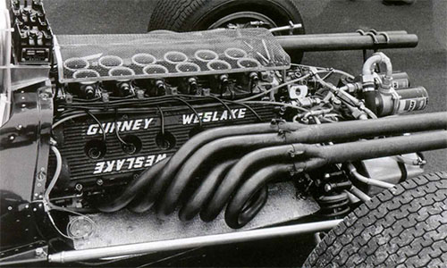
There were four valves per cylinder (two inlet and two exhaust) actuated by double overhead camshafts in each head. The valves were symmetrically inclined at a valve-included angle of 30° and sat in shallow pent-roof-shaped combustion chambers .Weslake didn't release details of the combustion space shape, but Edward Eves in Autocar magazine of 27-04-1967 reported that a source in the casting foundry had revealed the combustion space was 'lenticular' (a double-convex shape) with a hollow piston crown forming one convex side of the space and the pent-roof combustion chamber forming the other. Because of the narrow valve angle the camshafts were close together, so Woods was able to use a single cast-alloy cam cover to cap the top of each cylinder head. Separate inlet ports fed each cylinder and were at a steep downdraft angle to the cylinder head face, similar to the 500 Twin, where the angle was 43°. The two exhaust ports from each cylinder merged into one single elongated port within the head and exited parallel to the head face.
The austenitic steel inlet valves had an initial head diameter of 29.2mm and the Nimonic alloy exhaust valve heads were 25mm in diam. Inlet valve lift was 9.5mm while exhaust valve lift was 7.93mm. The valves were fitted with dual Terry's coil springs and as on the BRM V8 engine, were actuated via short small diameter bucket tappets above the valve springs with a bolted in iron carrier for each tappet. This reduced inertia and helped reduce camshaft torque allowing thinner gears to be used to drive the camshafts. The ratio of inlet valve head area to piston area was 0.32.
The camshafts were driven by a train of narrow spur gears (turning in ball bearings) off the nose of the crankshaft. The gears were contained within a separate split magnesium-alloy timing case that allowed the crankcase to add stiffness to the chassis without affecting the gear train alignment (Woods openly adopted this concept from the Ford DOHC Indianapolis V8 engine). The rev-counter drive was from the front of the right-hand exhaust camshaft.
The rifle-bored case-hardened camshafts ran in seven crowded roller bearings, each in a steel carrier that formed the outer race, which was held down by two cap screws to the top face of the head. The camshafts were made at the Rye works on equipment installed by Daniel, the cam profiles were based on those originally developed for the Shell Twin, but underwent minor modifications stemming from ongoing development work on the V12. No details of the final valve timing for the Type 58 V12 were released, but those for the Shell Twin are recorded below, indicative of the probable timing for the V12.
| Inlet valve opens - 66° BTDC | Inlet valve closes - 86° ABDC | (duration - 332°) |
| Exhaust valve opens - 89° BBDC | Exhaust valve closes - 41° ATDC | (duration - 310°) |
| Valve overlap period - 107° | ||
| The inlet valve was held at full lift for 109° of cam rotation | ||
6.3 - Crankshaft
To enable the engine to accelerate smoothly and rapidly, great attention was paid to the balance and weight of the crankshaft to reduce inertia loads. It was fully counterweighted with balance weights on webs - 2, 3, 6, 7, 10 & 11. The fully machined crankshaft was made by Laystall Engineering in alloy steel with nitrided bearing surfaces. It had seven main bearings with Vandervell lead-indium shells and the thrust washer was fitted on the centre main bearing. The main-bearing journals were 60.3mm in diameter and the crankpin journals were 41.3mm in diameter.
A spur gear on the nose of the crankshaft drove the timing and accessory gears and a light flywheel (with a toothed outer ring for the electric starter to engage) was attached to the end of the crankshaft by six hefty bolts. A Borg & Beck 7.25-inch twin-plate diaphragm- spring clutch was fitted to the flywheel.
6.4 - Reciprocating Parts
The narrow skirt-slipper pistons were forged in high-strength aluminium alloy and were supplied by Hepworth & Grandage. Weslake carried out the final shaping of the piston crowns by machining a small hollow in them to suit the combustion chamber shape. Interestingly, in April 1965 Weslake had filed a patent for a four-valve pent-roof combustion chamber with a projection between an intake and exhaust valve to promote axial swirl and a piston crown with a small recess beneath the spark plug location, and there is evidence of a very small projection between the inlet and exhaust valves in a photograph of the final Shell Twin's combustion chamber (see below). It appears the Eagle V12 adopted the piston shape but not the swirl projection, as Woods stated in an article he wrote for Sports Car Graphic magazine that the combustion chamber adopted in his V12 had no natural swirl (see also section 6.7). The finished weight of each piston was 230 grams and there were only two rings per piston, a Dykes L-shaped compression ring and an Apex oil-control ring.
The fully floating gudgeon pin was 19.1mm in diameter and weighed 72 grams.
The forged-steel I-section connecting rods were machined all over, weighed 320grams and of the same design as those used in the 2-litre V8 BRM. They were actually supplied by BRM after Weslake was unable to get a common outside supplier to make 'copies'. They were 123.75mm long centre to centre, and the big end was split horizontally. The cap had a pair of strengthening ribs and was secured by two bolts. Later in the engine's development, the connecting rods were made from titanium.
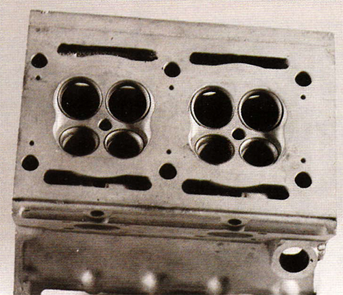
The Shell Twin combustion chamber.
6.5 - Induction and Fuel System
The inlet tracts were a compromise compared to those of the research Twins. The 60° V of the cylinder banks in the Eagle V12 didn't allow much room for the inlet tracts even with the engine's pivotal narrow cylinder heads. With two inlet ports per cylinder, it was not possible to replicate the individual inlet tracts of the Twins, which would have required 24 separate inlet tracts. Instead, the two inlet ports of each cylinder were merged into one by cast alloy elbows that bolted directly to the cylinder head port faces and turned the inlet tract tightly through approximately 20° to be vertical.
On top of this row of small individual castings on each cylinder bank was bolted a slide-throttle plate carrier which contained three rows of rollers on which a thin 1.6mm throttle plate slid. A further casting covered this plate and the rather narrow intake trumpets were individually mounted on this.
So the inlet tracts were not straight as on the 375cc and 500cc Twins, they had a tight bend. To be straight, the inlets from opposite banks would have had to crossover and their relatively short designed length for effective resonance tuning would have meant the provision of slide throttles would have been difficult. Butterfly throttles would have worked but this layout apparently wasn't considered.
The engine had Lucas fuel injection into the inlet tracts. The injectors were designed to use the needle and spring off the Lucas unit and were shaped to have minimal impact on the airflow and were initially positioned in the inlet trumpets above the throttle plate. (They were later repositioned to below the throttle plate in the cast inlet elbows, saving 3.2 kg in weight and giving lower fuel consumption by reducing fuel spray-back and better part-throttle response because of a lesser wetted area in the tract.)
The Lucas metering unit was mounted at the back of the engine driven by a toothed belt from a pulley on the rear of the right-hand inlet camshaft. The fuel supply was controlled from the end of the throttle plates via the operating mechanism of the metering unit and delivery pressure was 100psi.
A mechanical fuel-pressure pump was driven directly off the end of the left-hand exhaust camshaft to supply the Lucas metering unit. Woods modified a standard Lucas element and fitted it into a body of his own design. At maximum revs the pump could deliver 190 litres/hour at 140psi. This high mounting location would prove to aggravate fuel pick-up problems.
For starting, a small Mk2 electric fuel pump was mounted off the engine (on the back of the gearbox) to prime the mechanical pump and once the engine was running could be switched off.
6.6 - Exhaust System
Long up-swept exhaust pipes (hand-formed without joints) were attached by four bolt flanges to each of the siamesed exhaust ports and fed the exhaust gases from the front three cylinders and those from the rear three cylinders into two, three into one exhaust collector systems on each bank. Each collector had a long tail pipe and when the engine first appeared the four pipes had megaphone ends. The four megaphone pipes certainly looked impressive but after further experimental work were abandoned for straight-through tail pipes (although they made a temporary reappearance in trails in 1968).
6.7 - Ignition System
The engine was equipped with Lucas electronic ignition which fired a 10mm Champion G56 or G59 spark plug positioned centrally in each combustion chamber . This location gave the shortest flame travel for efficient combustion and Woods stated ,that this was particularly beneficial given the lack of natural turbulence in the form of 4-valve head they had adopted (this short-coming would be addressed by Keith Duckworth in his 4-valve cylinder head design).The spark plugs sat in deep wells in the one piece cam covers, with the ignition leads routed from the distributors alongside the inlet trumpets .
The ignition pole-wheel pulse trigger was driven from the rear of the right-hand exhaust camshaft with the electromagnetic pick-ups mounted on a cover on the back of the cylinder head. There were twin transistorised ignition 'black boxes' mounted behind the roll-bar, and two ignition distributors were mounted on the front of the engine each driven directly from the forward end of the shaft of the final timing gear that drove the two camshaft gears on each bank. Woods needed to keep the length of the engine to a minimum, so he modified the standard bulky Lucas distributor by doing away with its in-built rotor shaft and bearings and attaching the rotor to the end of the timing-gear shaft and clipping the distributor cap directly to the timing-gear casing. This reduced the distributor's length by nearly half to 90mm and also saved in total about 1.8kg in weight. Ignition advance was set at 44° BTDC.
A modified Lucas alternator was driven off the end of the first step-down gear's shaft in the timing case. The standard unit was both bulky and heavy, so Woods dispensed with all but the encapsulated stator and rotor and utilised one of the timing-gear shaft bearings to support one end of the rotor and designed a light-alloy bearing carrier for the other end. Drive for the rotor was taken through a small spring shaft which absorbed energy and protected it from rapid fluctuations in engine revs.
An electric starter motor was mounted on the right side of the engine's crankcase.
6.8 - Cooling System
A twin volute centrifugal water pump with a side-facing inlet was mounted at the bottom of the timing-gear case driven off the crankshaft nose via a step-down gear beneath it. The pumps delivery of some 115 gal/min (523 litres/min) was calculated from results obtained from the Shell Twin program and it had twin outlets that fed water via curved metal connecting pipes to galleries cast into the outer side of each cylinder bank. These galleries fed water through metering holes to each cylinder-liner recess and then up to the cylinder heads via transfer holes, the majority of which were under the exhaust ports.
Heated water was drawn off the inlet side of each cylinder head (from beneath the inlet ports) by a cast gallery bolted along the length of the head, with an outlet at the front of the engine. The outlets from both heads fed into a common collector and then to the front-mounted water radiator.
6.9 - Lubrication System
The engine had a dry-sump lubrication system with the oil pumps mounted at the front, low down on the left-hand side of the timing-gear case and crankcase. Mobil was a sponsor and its oil was used.
The oil scavenge pump was located in the underside of the crankcase and had three spur gears, the central one being driven. The drive was by a shaft which in turn was driven off the waterpump driveshaft. Each side of the pump operated separately, one side scavenged the front of the shallow magnesium sump, the other side the rear via a pipe and pick-up cowl. The oil pick-ups were positioned beneath the crankshaft and the scavenged oil and air from the crankcase was pumped out through the crankcase side via the mounting flange. It was then piped to an anti-frothing coil before passing through the oil cooler to the front-mounted oil tank holding 15.9 litres and it was stated no air breather was fitted (see Note 6.9.1).
In practice this system would prove inadequate and the engine was plagued with oil-scavenging problems throughout its life.
The gear-type oil pressure pump with in-built transfer passages was located in front of the scavenge pump and was gear-driven off that pump's drive shaft. The inlet to the pressure pump faced out to the side while its output fed directly to a metering block and pressure-relief valve bolted to the side of the crankcase. From there the oil was piped to two remote oil filters mounted above the gearbox and then piped back to a return boss on the side of the relief-valve housing. Pressurised oil was then fed into a gallery within the engine-block casting that supplied the crankshaft bearings. At the rear of each cylinder head was a light cover which also contained oilways transferring oil from the main block gallery to valve gear drillings which ran through both sides of each cylinder head over their whole length and fed the valve gear. Based on rig testing, the oil pump delivered up to 88.5 litres/min at 85psi.
Note 6.9.1: There were conflicting statements as to whether or not the engine was fitted with a crankcase breather. Several respected technical writers, in initial descriptions of the engine, stated that 'there was no air breather' and 'no external air vent is used'. However, reports about oil leaks and oil scavenging problems once the car was competing repeatedly refer to oil escaping from the engine breather near the top of the engine and one of those stating this, was Motor Sport's knowledgeable writer Denis Jenkinson. This writer has drawn the conclusion that as designed the engine didn't have a breather, but one was subsequently fitted to try and overcome crankcase pressurisation problems.
7 - Engine Development and Testing
Michael Daniel expanded the facilities at Rye, installing more equipment in the machine shop and engine test house so that major elements of the V12 could be manufactured and tested in-house. Unfortunately, much of the machinery acquired was outdated surplus Royal Navy equipment dating back to WW1 lacking Vernier adjustment, which did not allow the consistent precision machining required for such a complex design .This meant that each engine became essentially a 'one-off' unit with its components expertly fettled to fit together and thus lacking interchangeability with parts of the same kind.
The competition was more up-to date, Repco in Australia had installed their first Numerically Controlled (CNC) machine tools and went on to build the 1966 Championship winning Repco-Brabham RB620 V8 engine. Cosworth, similarly, was using CNC machine tools.
Work on building the Eagle engine progressed slowly, with the first castings not arriving until March 1966. It wasn't until early August 1966 that the first engine (5801) was assembled a job requiring 1,200 man-hours. It was compact, only 73.7cm long, 48.3cm wide and 54.6cm high and weighed 177kg (with clutch and starter but less the exhaust system). The engine was finally ready for dynamometer testing on the 18th.of August and the V12 was initially motored over cold by a small diesel engine driving through a step-up gearbox to check oil and water flows and pressures before firing up.
The first powered run was made with manual controls on the fuel injection, a calculated guess exhaust system and timings based on the 500cc twin cylinder tests and the engine was carefully run-in. The first test run produced over 300bhp @ 8,500rpm (equivalent to a BMEP of over 178psi) and by the end of the first week of testing, 364bhp @ 9,500rpm was recorded (equivalent to a BMEP of 166psi).
As promising as these figures were, they fell far short of the performance of the 500 Twin which had realised a peak power BMEP of 207.9psi @ 10,000rpm. With a new engine design there is normally scope for development in valve and ignition timing and refinements to the induction and exhaust, but that development had already been done on the twin-cylinder research engines upon which the V12 design was based, so there was less scope for further development to close the 'gap' .Clearly what was different was the tight merging of the inlet ports and the bend in the inlet tracts on the V12 compared to the arrow straight and individual inlet tracts of the 375cc and 500cc Twins. This reflected the difficulty in transferring the freedom in scope for inlet and exhaust manifolding on a research engine to a multi-cylinder engine for actual use and must have had an adverse effect on the engine's breathing.
Gurney was dismayed at the changes to the form of the inlet tracts and Weslake was far from happy with the results too. Nevertheless the team felt confident enough to see what the engine could do in the car so they decided to enter it in the Italian GP, only one week away.
Type 58 Gurney-Weslake V12
8 - The Eagle Grand Prix Car
Once he had Goodyear's backing, Gurney hired Len Terry (who had worked at Lotus and designed the car that won at Indy in 1965) to design his Eagle racing cars. Terry joined AAR after the Indy win and moved to Santa Anna in late September 1965 to commence the design of the Eagles. The design had to be adaptable to both USAC oval racing and Grand Prix road racing.
Terry produced a fully tubular aluminium alloy monocoque chassis that had booms that extended along the sides of the engine bay to a rear bulkhead that braced their ends .For Indy racing it was fitted with the Ford DOHC Indy V8 and this determined the size of the engine bay, so the Weslake V12 would be a tight fit, forcing Woods to keep its length as short as possible by limiting attachments at the front. The Indy chassis was constructed of 16sgw aluminium while the Grand Prix chassis was made in thinner 18swg, this together with other measures meant the F1 car was about 24kg lighter than the Indy version. The GP chassis design was designated Mark 1 and the Indy chassis design Mark 2.
The first F1 chassis 101 was completed by early 1966, but as the V12 engine was far from ready Gurney purchased four 2.7-litre Coventry Climax FPF four-cylinder engines to use in the interim. A Hewland 5-speed DG300 gearbox was fitted. The Climax-powered car had its first test at Goodwood on the 8th of May and made its F1 debut in the Belgian GP in June, impressing with its fine workmanship and presentation. The car had good handling which was further refined over the next period and showed its potential with a best place finish of 5th in the French GP and by qualifying 3rd for the British GP in July. The second chassis 102 was completed and fitted with the V12 engine (but not run) ready for its debut at the Italian GP on 4th September. Len Terry left AAR at this point in time and was not involved in any further development.
9 - The V12 Eagle in the 1966 Season
9.1 - The Competition in 1966
When the V12 Eagle debuted at Monza, two other new engines were also present to add to the opposition. Ferrari produced a new engine for their 312 F1 car, the Tipo 237 engine, a three-valve-per-cylinder version of the GP V12 developing 380bhp @ 10,000rpm (which would win the race) while Honda appeared with its new car, the RA273 powered by a 90° V12 four-valve engine (RA273E) developing 400bhp @ 11,000rpm which was offset by the car being the heaviest on the grid at 742kg.
The rest of the opposition at this stage in the season comprised a mixed bag. BRM had finally got their big and troublesome H16 to a state where they would race it, the heavy P75 engine developing around 400bhp, Cooper's T81 car was powered by a Maserati Tipo 9 V12 producing 360bhp which was developed from the engine used in the 1957 250F T2 Grand Prix car. Lotus had its type 43 car powered by a BRM H16 engine and as back-up, the type 33 car fitted with a 2-litre version of Coventry Climax's FWMV V8, while Mclaren used a Ford DOHC Indy engine reduced in capacity to 3 litres in their M2B chassis that produced just over 300bhp and lot of noise but had a very narrow power band and was far from reliable. Brabham had their BT19 and BT20 cars powered by the Repco-Brabham RB620 V8 engine which was light, reliable and developed 300bhp with a wide power band.
9.2 - Eagle V12 Race Performance 1966
The blue-and-white V12 Eagle created quite an impression when it appeared in the Monza paddock. People were surprised at the compact size of the engine with its single cam cover on each cylinder bank, with the words "GURNEY 3 litre WESLAKE" cast into their ribbed tops. It was so compact that the body panelling enclosed virtually all of its mechanism and the car was one of the lightest at 580kg. The engine certainly looked purposeful, with its double row of inlet trumpets (screened by a rectangular wire mesh cover) and up-swept groups of exhaust pipes ending in four megaphones that emitted a very hard exhaust note, personifying the Return to Power of the new GP formula.
Gurney had also entered the Eagle-Climax for Phil Hill to drive on the proviso that the V12 Eagle qualified for the race. The V12-engined car was still being finished off in the paddock when practice started, so Gurney and Hill practiced in the 4-cylinder car which was carrying the same number as the V12 car, which confused the timekeepers. When Gurney eventually took the V12 Eagle out to practice, problems with the fuel pumps and pipework caused air locks to form on throttle lift-off and then fuel starvation under acceleration, so the best time he could record was 1.51.7, over 20 seconds off the pole time of Parkes in the Ferrari V12 of 1.31.3. Both Gurney and Hill put in times on the 4-cylinder Eagle, Gurney using the number of the V12 car and setting a time of 1.37.6, which was accredited to him for the second-last grid position in the V12. Hill failed to qualify with a time of 1.40, as only the fastest 20 cars were allowed to start. In the race, Gurney was late coming out onto the grid because Tim Wall was still working to rig-up an aerating tank to try and rectify the fuel starvation problems on the V12. Once the race started, Gurney had to pit on lap 1 for further work, as the full fuel tanks aggravated the problem; he then set off again but had to come in and out of the pits for attention until finally the car began to go properly and sounded strong, setting a time of 1.35. But he then had to retire on lap 8 because of very high engine-oil temperature and a fuel leak. A troubled start for the V12, but there were signs of promise. Scarfiotti in the Ferrari 312 F1 won the race and Brabham clinched the World Drivers Championship driving his own Brabham-Repco car.
The next race was the United States GP at Watkins Glen on the 2nd of October. Post Monza, the V12 engine was stripped down and had shown no mechanical faults, but the issues with cooling and lubrication remained. The problems with fuel feed were said to have been rectified but not track tested.
Both cars were taken to North America and the team was accompanied by Michael Daniel who told the motoring press, that the V12's effective operating range was from 6,000 to 9,750rpm and that a second engine (no.5802) was running, another was almost complete and three more are under way. Bob Bondurant was engaged to drive the 2.7-litre Eagle-Climax, replacing Phil Hill who had suffered a hernia.
Gurney in the V12 Eagle was plagued with problems in practice, the engine pumping oil out all over the place and overheating. As the engine was now being driven for longer at race pace, its inherent poor oil scavenging was becoming more of a problem. Further practice was thwarted when the drive from the end of the camshaft to the ignition pole-wheel impulser sheared and when the old problem of fuel starvation also reappeared. Overnight one of the fuel cells on the V12 Eagle was changed after a leak was found and an attempt was made to stop oil coming out of the engine seals and breather. On the second day of practice both cars were out early, Gurney in the V12 was beginning to get things sorted and although his lap times were not good, he was timed on the straight faster than any other car and finally managed a time of 1.11.03 for 14th on the grid, 2.61 seconds slower than Brabham's pole time. Bondurant in the Eagle-Climax achieved a time of 1.12.4 for a position two spots behind Gurney on the grid.
In the race, Bondurant in the Climax-engined car went off the track on lap 5 avoiding debris and had to retire while Gurney in the V12 worked his way up to 8th place by lap 12, only to retire on the next lap with clutch slip due to oil getting on the clutch plates caused by oil scavenging problems, the car had not been running well from the start with fuel starvation and ignition timing problems. The race was won by Jim Clark in a Lotus-BRM H16, giving what was to prove that engine's only race win.
Before the next race, the Mexican GP on the 23rd of October at Mexico City, the Weslake V12 engine was returned to Rye for attention to the various problems bedevilling it, but again it was not track-tested before it was sent back.
Both the V12 and the Climax-engined cars were entered for Gurney and Bondurant and early in practice Gurney went out in the V12, but it was still misfiring from fuel-feed problems and each time he came into the pits the car was smothered in aerated oil from the breather on top of the engine. A new nosecone with a wider intake was tried to allow more air to pass through the radiators to combat high engine temperatures compounded by the altitude of the circuit. At the close of first practice Gurney took the 4-cylinder Climax car out and was over 2 seconds faster than Bondurant in the same car. On the second day of practice the V12 Eagle was still pumping out oil even though an air/oil separator was fitted, poor crankcase scavenging with the oil building up in the heads was the problem. Bondurant was told to take it out and drive at a speed that would keep crankcase pressure down and hopefully stop oil being put down on the track, his best lap time was 2.02.88. The problems with the V12 Eagle so affected its lap times that even though it was 18mph faster down the straight than the 2.7-litre Eagle-Climax, Gurney had set a time slightly faster in the Climax car than he did in the V12, so he decided to race it and Bondurant was given the V12 to race with a rev limit of 8,000 instead of the normal one of 9,800rpm in the hope that it might last. Gurney's time of 1.54.93 with the Eagle Climax placed him 9th on the grid, 1.75 seconds slower than pole, Bondurant started last in the V12.
In the race, right from the end of the first lap Bondurant in the V12 suffered misfiring due to fuel vaporisation and with this problem (and his lower rev limit) he ran last until he retired on lap 24 with fuel boiling. Gurney in the Climax car had worked up to 5th place by mid-race distance and despite a misfire held that position right to the end of the race, which was won by Surtees.
9.3 - 1966 in Review
AAR had entered the V12 Eagle-Weslake in three Grands Prix and it had failed to finish in all three, although it did show glimpses of its potential. The car/engine combination suffered from a lack of track testing before it was raced, so consequently most of the time was spent addressing installation problems and making it race-ready.
The main issues that were revealed were:
- - Fuel feed problems under the effect of G forces that caused fuel starvation, not helped by the high mounting position of the primary fuel pump
- - Ignition problems that caused spark over advance
- - Inherent poor crankcase oil scavenging that caused oil to collect in the cylinder heads as more laps were run, resulting in high oil temperatures, oil blow-by and loss of power.
Much work needed to be done, including ongoing power development, so the team returned to their base at Rye and chose not to enter the V12 car in the South African GP on the 2nd of January and concentrated on preparing it for the start of the European season.
10 - The V12 Eagle in the 1967 Season
10.1 - Engine Development 1967
When the first V12 engine arrived back from Mexico, Weslake had it pulled down so that the inlet ports could be worked on to try and rectify the lack of specific performance compared to the 500 Twin. Larger, 30.5mm diameter inlet valves were fitted and the megaphone exhausts were replaced by straight pipes. By early January the first engine had completed 45 hours running on the dynamometer and the second V12 engine (no.5802) was complete and running too. Weslakes claimed to have overcome the crankcase pressurisation problems and by February had fixed piston-ring problems that had caused high oil consumption. To help address the oil burning/loss problems and high oil temperatures, additional oil capacity was added by fitting the cars with the Len Terry-designed 'bird bath' automatic oil-replenishing tank as already used in the Indy cars, which held 18.2 litres. Work was also spent experimenting with upstream and downstream injection into the inlet trumpets, but the main effort went into building more engines.
By March the engine was reported to develop 400bhp @ 9,500rpm and 410bhp @ 10,000rpm (the latter equivalent to a BMEP of 177.6psi, still far short of the 500 Twin's performance). It had a good range of power though, pulling strongly from 6,000rpm without any flat spots and it idled smoothly.
Mobil withdrew their support in 1967 and by mid-year AAR had signed up with Castrol for lubricant. A third chassis (103) had been built in Santa Ana to be fitted with a V12 engine and Richie Ginther had been taken on to drive it. Harvey Aluminium of California became an important backer in 1967 and Gurney turned to them for advice in reducing the car's weight which was 80kg over the Formula minimum.
10.2 - The Opposition in 1967
The Eagle V12 had strong opposition in 1967. World Champions Brabham had a new BT24 chassis powered by a new purpose-built Repco-Brabham RB740 engine with 330bhp. BRM would persevere with their H16 engine with 420bhp in 8-pin configuration, Ferrari had a revised three-valve-per-cylinder engine with 390bhp in their 312F1, Honda had their 400bhp V12, Mclaren would field a new car powered by BRM's customer two-valve V12 with 370bhp, Cooper had a new three-valve-per-cylinder Maserati Tipo 10 engine delivering 380bhp, while Lotus would early in the season field its advanced Type 49 powered by the epoch-making four-valve per cylinder Ford Cosworth DFV engine developing 405bhp.
10.3 - Eagle V12 Race performance 1967
While the V12 engine was being further developed at Rye, in January, Gurney entered the Climax-engined Eagle in the South African GP and got as high as third before retiring with broken suspension. The car (chassis 101) was then sold complete to a private party and all focus was put to AAR's next entry of two V12 cars in the Race of Champions held at Brands Hatch on the 12th of March, a race comprising two 10-lap sprints and a 40-lap final.
There were no works entries from BRM or Lotus in the race, but strong competition was provided by works entries from Brabham, Cooper, McLaren, Ferrari and Honda and a Tim Parnell-entered works H16 BRM. The V12 Eagles set the pace in practice sounding very healthy and running sweetly, with Gurney setting the pole time of 1.32.2 for the first 10-lap heat with Ginther third fastest, 1.4s slower. Surtees on the Honda V12 was second fastest, sandwiched between them on the front row.
At the start the two Eagle-Weslakes outaccelerated the Honda with Ginther leading Gurney into Paddock Bend. On lap two, Ginther moved over and let Gurney through to lead the race and go on to win and set the fastest lap of 1.32.6. Ginther finished third after Surtees on the Honda passed him for second place.
The starting order for Heat 2 was the finishing order of Heat 1 and again the Eagles outdragged the Honda at the start and Gurney went on to an untroubled win with Ginther second.
In the 40-lap final for the Daily Mail Trophy, the cars lined up in the order they finished in Heat 2. Gurney and Ginther led off again and although Gurney continued to lead the race his Weslake V12 was showing signs of losing power, with a lot of oil being pumped out of the breather into the catch tank and then slopping over, and he had difficulty getting away from Brabham (who had passed Ginther) before Brabham pitted and retired. Then Ginther retired on lap 37 with steering problems, letting Bandini in the Ferrari into second place where he closed on Gurney's ailing Eagle, which nevertheless held on to win the race, with the Ferrari only 0.4 seconds behind.
Weslake claimed that the oil smoke from Gurney's car was caused by oil from the breather getting onto the exhaust pipes and not from piston-ring problems as that had been rectified two months earlier. Altogether a good showing, with wins in all three races but worrying signs of the ongoing engine-oil scavenging problems.
After the race, a minor controversy developed within the correspondence pages of the English magazine Motor Sport regarding the fuel used by the winning Eagles. Denis Jenkinson (DSJ), the magazine's race reporter, stated in his report that the team had no fuel contract with the major companies. He was told by the team that they had purchased their fuel on the way to the circuit and that it was Jet petrol, but Jenkinson then went on to say that it could have been any brand and was possibly Esso Golden.
This comment drew a response from Sir Anthony Stamer of Jet Petroleum which was published in the Letters column of the next issue of the magazine, in which he challenged Jenkinson's 'guess' that the team had used Esso Golden. He went on to explain that the two Eagle-Weslake cars used perfectly standard Jet 100 octane fuel in testing, practice and winning at Brands Hatch, which had been obtained from the pump at Peter Berthon's Jet petrol station at Rye and transported to the circuit in drums. DSJ apologised for the unintentional slight on Jet's quality and that seemed to be the end of the matter.
Then two months later, a letter was published in the July issue of Motor Sport from Ray Cunningham, the Shell Motor Racing Manager (UK) in which he emphatically stated that the two Eagles were filled with a total of 66 gallons of Super Shell with ICA for the race, the fuel being obtained from Shell's retail outlet in the Brands Hatch paddock.
This drew an immediate response from Stamer of Jet Petroleum which was published in the same issue. Stamer wrote that upon reading Cunningham's claim, he contacted AAR, and team manager Bill Dunne reconfirmed that all practicing by both Eagles was completed using Jet 100-octane petrol and that Gurney's race winning car used Jet 100 throughout the whole meeting. But with regard to Ginther's car, it used Jet 100 in the two heats but in the final it was felt that supplies of Jet fuel for it were perhaps dangerously low, so Mechanic Joe Ramirez obtained some 2-3 gallons of BP fuel as a top-up (which Stamer admitted he wasn't previously aware of) and AAR refuted Shell's claim.
The matter was finally clarified and explained when a detailed letter from AAR team manager Bill Dunne was published in the September issue of Motor Sport magazine in which he referred to the 'fuel controversy' and reiterated exactly what petrol was used by them at the Race of Champions and what brand of petrol they subsequently used. In the letter Dunne stated:
"The fuel that was fed into the two Eagles before leaving Rye was purchased from the Jet petrol station owned by Peter Berthon, located at Winchelsea Road, Rye, Sussex. As Sir Anthony Stamer states in his letter in your July issue, we ran both cars on this petrol during both practice and the heats. As we were running out of fuel we topped up Dan's car for the final with the remaining Jet but Richie's car was topped up with fuel which we bought from the BP outlet at Brands Hatch. Before the heats, Shell had graciously offered to supply us with whatever we needed. It was because of this offer that we chose to run on Shell until such time as we signed an oil contract. As a result we ran on Shell at Monte Carlo, Zandvoort, Spa and Le Mans. As we have now signed an oil contract with Castrol, we shall no longer be running on Shell. I would like to state, however, that both the service and the products supplied to us by Shell were excellent."
Following the win in the Race of Champions, the focus went on preparing for the start of the European Grand Prix season. In April, Weslake had their first engine blow-up after 120 hours of running, giving them insight into how long an engine would last and what would break. Back in Santa Ana, AAR were working to implement recommendations made by Harvey Aluminium to use magnesium instead of aluminium in the monocoque chassis and to replace steel suspension parts with titanium ones so as to reduce the weight of the car. During April AAR fabricators Pete Wilkins and Dick Weber started building the fourth car (chassis 104) from these materials, which was nicknamed the 'mag-ti' car, with a view to have it ready for the Dutch GP in June.
AAR's next entry was for the Monaco GP in Monte Carlo on the 7th of May. AAR was not yet officially recognised by the organisers as a works team and therefore were not an 'invited' entry, so Gurney and Ginther were among eight cars that had to qualify for one of the five places left on the 16-car grid. In first practice, Gurney had a welded joint in a drive-shaft shear, luckily without any other damage. Gurney then took over Ginther's car and qualified 7th with a time of 1.29.3, 1.7 seconds slower than Brabham's pole time of 1.27.6. Ginther with a time of 1.31.1 failed to qualify for a place. For the race Gurney's car had a shorter nose fitted to avoid the risk of the normal long 'beak' getting bent and he made a good start quickly moving up to third place only to retire on lap 5, when the toothed belt drive to the engine's Lucas injection pump broke.
Indianapolis was then the focus for AAR, but Ginther stepped down from his drive as he felt he was no longer competitive. He did go to Goodwood though in the last week of May, to test the new lightweight car for the team (chassis 104) in preparation for the next F1 race, the Dutch GP at Zandvoort on the 4th of June. The 104 car with its close riveted hot-formed magnesium skin and titanium suspension, pedals and various other parts was a superb example of the skilled craftsmanship at AAR and resulted in a weight reduction of 40kg to bring the total down to 540kg. Part of this weight loss was attributable to the work of Pete Wilkins in crafting the exhaust system of the V12 in titanium, which reduced its weight from 16.6kg for the steel system to only 7.5kg for the titanium one.
The Dutch GP saw the debut of the Lotus 49 powered by the Ford Cosworth DFV V8, raising the level of the competition significantly. AAR had three cars and a new spare engine for Gurney at Zandvoort (no one had yet been found to replace Ginther), the two from Monaco and the new 104 car which drew admiration from the opposing teams for its workmanship and skilled welding. When practice started the Eagle and the Lotus set the pace and Hill finished fastest with Gurney only 0.2s behind. For the next day of practice a different, more powerful engine was fitted in Gurney's lightweight 104 car and again he was fast, until oil started leaking from the rear main bearing, losing eight litres in six laps, so Gurney pitted to top up the oil tank and went out again only for the problem to amazingly cure itself to the joy of the team. Gurney went on to set a very fast time of 1.25.1, only to be bettered by Hill with a time of 1.24.6 for pole. In the race Hill led away and Gurney had a hesitant start because as he accelerated away, fuel sprayed out of the tank overflow straight into the engine's inlets causing a rich mixture and Gurney was pushed back to third. From then on the engine did not run properly with injection mixture problems and Gurney pitted on lap 7 to have adjustments made to the fuel metering unit. He went out again but the engine sounded horrible and he retired on lap 9 with a broken fuel injection metering unit. Disappointing, but nevertheless the Eagle with the Lotus were timed fastest on the straight at 165mph. Clark took a maiden victory for the new Lotus-Cosworth.
The next entry was for the Belgian GP at Spa on the 18th of June and Gurney had the lightweight Eagle 104 and a spare car and engine. The Weslake engine in the 104 car was said to produce 416bhp @ 10,000rpm and had the fuel injector nozzles placed below the throttle slides in the inlet elbow castings and squirting upstream into the airflow. This arrangement gave better top end power and was fitted to other engines in future races where this characteristic was beneficial. A few days earlier, Bruce McLaren had tried out an Eagle at Goodwood and AAR had hoped to enter him to drive the second car but were short of a good spare engine, so this didn't eventuate. Practice started and the 3-litre cars showed their potential easily breaking the lap record set by Phil Hill in May driving the 7-litre Chaparral 2F. Clark was fastest with Gurney next, the Eagle running well. On the second day of practice Clark set the pole with a time of 3.28.1, with Gurney second fastest with a time of 3.31.2. A wire mesh grill was fitted to the Eagle as a stone had holed the radiator. At the start Clark led off but Gurney's Eagle hesitated getting of the line and dropped back to fifth. By lap 5, Gurney had moved up to third place behind Clark and Stewart in the H16 BRM, but then Gurney's engine suffered from a misfire at high rpm and he made a quick pit stop on lap 12 to report that the fuel pressure from the mechanical pump was low. He then rejoined in second place behind Stewart, as Clark had also pitted. Stewart and Gurney continued on, the Eagle's fuel pressure fluctuating between 60 and 120psi instead of the normal 140psi. (One contemporary report stated that it was later found it was actually a faulty gauge. Nevertheless, the misfire persisted and was most noticeable at high speed on the straights, where at times the top speed dropped down to 186mph. Possibly the fault was the spark advance varying due to problems with timing impulses from a faulty ignition trigger wheel, as would be encountered in later races.) Gurney was concerned that the detonation might harm the engine, but then on lap 17 the leading BRM developed gear-selection problems and Gurney started to close, passing Stewart on lap 21 to take the lead. DSJ in his race report wrote that the Eagle looked and sounded superb, the only fault was oil spraying out of the catch tank onto the exhaust pipes making a lot of blue smoke (the misfire apparently didn't occur where DSJ was watching). Gurney pressed on and went on to win the race at record speed and to also set a new fastest lap of 3.31.9 on lap 19, an average speed of 148.85mph. This was the first win by an American driver in an American car (albeit with considerable British input) in a Grande Epreuve since 1921 when Jimmy Murphy won the French GP in a Duesenburg.
This was an impressive performance, one year on from the debut of the Eagle-Climax at Spa. Gurney said that the car was as fast as the Lotus on the straights and that when it was on full song he was pulling 11,200rpm in top gear on the long run down to the Masta kink, equivalent to 196mph. This was more than 1,000rpm over peak power revs, no doubt aided by the long down-hill gradient of the straight. This indicated that the gearing was a compromise to aid the long climb back up from Stavelot. The engine in Gurney's winning car had done some laps at Goodwood prior to the Belgian GP and after taking the chequered flag had covered some 770 racing kilometres without being taken out of the chassis, the best reliability yet.
Around this time, Peter Wilkins approached Tony Southgate on behalf of Gurney to see if he was interested in joining AAR as chief chassis designer. Southgate accepted and would start at Santa Ana in October to work on the 1968 cars for Indy and F1.
The French GP held on the Bugatti Circuit at Le Mans on the 2nd of July was the next entry for AAR. Mclaren was entered to drive chassis 102 while Gurney had 104 again. Gurney set the third fastest practise time in 1.37.0, 0.8s slower than Hill's pole time in the Lotus-Cosworth, while Mclaren qualified fifth on the next row with a time of 1.37.6 after he had an engine change. The original engine had broken an oil-scavenge-pump driving gear. In the race Gurney got away well and by lap 23 was second behind Brabham once both leading Lotuses went out. McLaren was in 8th spot, his Weslake V12 engine not giving the power it had started with, as evidenced when he could not even outaccelerate the Cooper-Maseratis. Mclaren pitted and it was found that the tongue-drive to the ignition trigger wheel was shearing, retarding the ignition, so the car was retired (the unique spark trigger wheel driven off the end of the exhaust camshaft causing problems again). On lap 38, Gurney's engine started misfiring and on lap 41 he stopped on the track with no injection pressure, as a small rigid pipe between the injector unit and the pressure release valve system had fractured at the union itself.
The next event for the Eagles was the British GP at Silverstone on the 15th of July, Gurney again driving the 104 car while McLaren had number 102. The engines had been fitted with flexible piping to the injection metering unit after the failure at the last race and had the fuel injectors positioned beneath the throttle slides. On Gurney's car, the titanium front-suspension rocker arms were replaced with the standard steel ones in a search for more rigidity. Both cars had trouble in practice, McLaren had problems with the differential and then after that was fixed the engine broke a connecting rod (just above the big end eye) and the mechanics had to fit the spare engine over-night, while Gurney wasn't happy with his brakes. They finished up with Gurney fifth fastest on the second row with a time 1.1s slower than Clark's pole time of 1.25.3 while McLaren was tenth fastest with a time of 1.28.1. Prior to the start of the race both cars were still being worked on and in the race, Mclaren retired on the 14th lap with smoke coming from the Weslake engine with another broken connecting rod. Gurney was running in sixth spot but had trouble keeping up and on lap 34 he retired in the pits with terminal clutch slip caused by oil leaking from a faulty rear main-bearing oil seal.
The German GP at the Nürburgring was next on the 6th of August and AAR entered Gurney in car 104 and Mclaren in car 102. The engine in Gurney's car was new, no.5805, and was fitted with the earlier form of fuel injection with the injectors located above the throttle slides. This system gave a better spread of power at the loss of a little at the top end. McLaren's engine was no.5804 and was fitted with the injection set-up with the injectors located below the throttle slides squirting upwards.In practice, McLaren was delayed as his fuel-injection metering unit was not working properly, but he eventually set a time of 8.17.7 for fifth place on the grid. Gurney had set an identical time but as he did it first he was in fourth place on the grid, sharing the front row with Stewart, Hulme and Clark who had pole with a time of 8.04.1. At the start Clark led and the race settled with Gurney in third and Mclaren fourth, but on the fourth lap Clark's Lotus suffered a loss of tyre pressure and slowed, whereupon Gurney passed Hulme to take the lead. On the same lap McLaren stopped out on the circuit with smoke and oil coming out of the Eagle. The car had been bottoming out on the track so badly that it had worn away the oil-scavenge pipe from the sump. From there on Gurney easily led the race, the Weslake engine running beautifully, stretching his lead over Hulme and setting a new lap record of 8.15.1 on his sixth lap, but then on the 13th lap with a lead of 42 seconds and only two laps to the finish and an easy win, a universal joint on a driveshaft broke, which flayed through an oil line forcing retirement and costing Gurney the race.
At the next race, the Canadian GP on August 27th at the Mosport circuit, Gurney was the only Eagle entry as McLaren was now driving his own car powered by the new BRM V12. The Eagle was aluminium chassis 103 but it was fitted with all the titanium components from the magnesium chassis 104, which was undergoing an overhaul for the end-of-season races. The engine in the car was no.5805 with no.5804 as a spare. In practice Gurney's engine wasn't pulling well and as it had twice broken the belt which drove the fuel injection metering unit, it was changed for the spare no.5804. Gurney set a time of 1.23.4 for fifth spot on the grid, one second slower than Clark's pole time. It was a wet race and Gurney pitted twice for goggles and for mixture adjustment to give better performance at low revs and drove on to finish third, one lap down on the winner Brabham.
The Italian GP at Monza was next on the 10th of September and AAR had engaged Scarfiotti (last year's winner but no longer on the Ferrari F1 team) to drive Eagle chassis 103 while Gurney had the magnesium chassis 104 with improvements to various suspension items. Scarfiotti put in a large number of practice laps in his Eagle only to pit with steam coming from the overflow and signs of a cylinder liner Cooper-sealing ring having failed. Gurney had a new engine fitted to his car while his old one replaced the damaged one in Scarfiotti's. Practice was affected by rain and Gurney qualified fifth with a time of 1.29.38, while Scarfiotti was in tenth spot, 1.42 seconds slower. There was a confused start to the race and Gurney led the opening lap only to be passed by Clark on lap 3. However, the Eagle had the power to stay with the Cosworth-engined Lotus on the straights until lap 5 when Gurney coasted into the pits to retire with oil streaming from under the engine caused by a broken connecting rod bolt. On the very next lap Scarfiotti also coasted in to retire with a dead engine,the scavenge-pump housing had broken and damaged the timing gears.
For the United States GP at Watkins Glen on the 1st of October, AAR had planned to enter two cars, but with three engines damaged at Monza, only Gurney was entered in chassis 104 now fitted with a ZF-type differential and according to reporter John Blunsden, the best engine produced by Rye to date developing 416bhp @ 10,250rpm and more significantly 354bhp @ 8,000rpm. The latter figure is a fair indicator of the engine's torque peak and equates to 232.4lb ft and a BMEP of 191.7psi.The engine was also fitted with new German drive belts to the fuel injection pump. Gurney achieved a practice time of 1.06.64, good for third place on the grid, before his engine tightened up when the scavenge pump broke. This required work on the engine to check it over and to replace the scavenge pump. In the race, Gurney held third place until lap 21 and then had to retire on lap 24 with broken suspension.
The final race of the year was the Mexican GP in Mexico City on the 22nd of October and again only Gurney was entered, in chassis 104 with strengthened suspension. After Watkins Glen one engine had been sent back to Rye for overhaul and another had been returned as spare. Gurney set a practice time of 1.48.1 for third place on the grid, 0.54 seconds slower than Clark's pole time. At the start Clark hesitated and Gurney ran into his exhaust pipe puncturing the Eagle's radiator and damaging the nose of the car. Gurney got away last and continued on with water pouring out, but had to retire on lap 4 because the engine began to overheat.
10.4 - 1967 in Review
A year of highs and lows for Gurney's Eagle Formula 1 team. After the significant win in the Belgium GP the only other placing was third in the Canadian GP. The engine had shown real power and the car's handling was very good, but a string of retirements robbed the team of further success. Counting only the final race in the Race of Champions event (the two 10-lap heats were not really a test or indicator of reliability) the race performance of the V12 Eagle in 1967 was:
- - Race Starts: 16, retirements: 13 (a retirement rate of 81.25%)
- - Of the retirements, 8 were directly engine-related, accounting for 61.5% of the retirements
- - Of the 8 engine failures, 4 were major engine failures while the other 4 were ancillary failures
Only two of the retirements were caused by accidental damage, all of the others were from mechanical failures, highlighting the lack of prior testing to sort out development issues and race-worthiness. When engine failures that occurred during race practice are also considered, a truer perspective of the problem is obtained. In the eleven races entered, during practice there were a further five engine failures bringing the total for practice and the races to 13, an engine failure rate of 1.2 per event. What was even more telling was the repeated failures in three specific areas: connecting rod breakages, oil-scavenge pump failures and broken drive belts to the injection metering unit. The problems were not being addressed and pointed to a lack of time and resources/funding. Gurney was far from happy with the repeated engine failures hampering the team's efforts and putting a drain on the team's limited funds.
11 - The Split with Weslake and Co.
Gurney and his team felt that the engine design was good, but that the machining tolerances and assembly by Weslake wasn't precise enough, so in October they negotiated a new monthly-basis agreement with Weslake that would take effect from November. Under the agreement, AAR would assemble the engines from parts made by Weslake and AAR hired Doug Orchard (formerly of Vanwall) as chief engine fitter to supervise the work of assembly and maintenance. Robert Richards, who had worked at Cosworth, also joined AAR to assist Orchard. This arrangement with Weslake had a very short life and failed badly, with multiple engine failures in the next Grand Prix entered in January 1968, forcing Gurney to take more positive control.
Reluctantly, Gurney decided to sever AAR's links with Weslake and to set up his own engine shop to build, test and maintain the engines in a controlled and standardised way. He tasked Bill Dunne to locate a new factory and to find new suppliers for castings and machined parts. Dunne arranged the lease of single-story 560-square metre building on premises in Ashford, Kent, about 24 kilometres northeast of Rye, big enough to accommodate engine building, dynamometer test cells and race-car preparation.
But it took time to set the new operation up and in the interim the team was still based at Rye. It wasn't until the 1st of April 1968 that first the office staff moved into the new premises, together with Aubrey Woods who had left Weslake to join Gurney at Ashford and head up the engine team as chief engineer. Then on the 15th of April the chassis work was moved there and finally on the 1st of May the engine shop under Doug Orchard was established with the experienced engineer Peter French (ex-Coventry Climax) placed in charge of research and development. This meant that AAR's operation was then entirely based at Ashford (although the dynamometers were still to be installed).
With this change the team reverted to its original title of All American Racers.
The split with Weslake and Co. was felt very deeply by Harry Weslake .It was reported that Weslake would from then on only do special development assignments for AAR.
12 - The V12 Eagle in the 1968 Season
12.1 - Engine Development 1968
During this acrimonious time, work still proceeded at Weslake on engine development over the winter months. A key issue that needed addressing was the engine's oil scavenging problems and although some changes were made, Gurney was to later state that he felt it required a re-design rather than a fix as the location of the pick-ups for the scavenge pump were poorly conceived.
Small modifications were made to the combustion chambers and larger 33mm-diameter inlet valves (making inlet gas speed lower than optimum as RPM stayed the same) together with smaller exhaust valves were fitted in the search for more power and downstream fuel injection with the nozzles below the throttle slides had been standardised for better response. French worked on reducing frictional losses in the engine and improving its general execution to improve reliability. John Bolster of the weekly British magazine Autosport reported in the 23rd of February 1968 issue that he had visited the works at Rye and had spoken to French and been told the results of the winter engine test programme which were quite amazing. He revealed that the lowest power reading from the Weslake V12 was 432bhp while the highest figure obtained was 451bhp. An average figure which could be duplicated on any engine was a resounding 442bhp @ 10,500rpm, with maximum torque occurring at 8,500rpm. Bolster also reported that the power curve dipped very sharply after the peak at 10,500rpm. The valve gear was safe to 12,000rpm but development was focused on filling out the middle part of the power curve. These power figures were more in line with the predicted power based on the results of the 500 Twin and in an interview in the 10th of May issue of the same magazine Gurney also referred to these same power outputs, adding that the 'average' engine also developed over 300bhp @ 7,000rpm.
But Gurney and his team were later to be brought rudely down to earth as to the engine's actual power.
In May when AAR split with Weslake and Co. and completed their move to Ashford, they lacked engine test facilities of their own as the engine dynamometers were still being installed, but at the end of that month Tony Rudd of BRM kindly offered them the temporary use of his test facility at Folkingham to run power tests. On the BRM dyno, AAR were most disappointed to find that the Weslake-based engine they tested only gave 385-390bhp, a staggering 42 bhp less than the lowest figure claimed by Weslake on their dynamometer. Even more telling was that on the same dyno, BRM's own two-valve V12 had produced 389bhp @ 10,000rpm. Weslake's dynamometer had required major repairs after the winter test sessions and clearly had been giving optimistic readings. Perhaps the quoted figures were only flash readings which could not be sustained. The team at the new engine facility at Ashford had much to do to address the engine's shortcomings.
Providently, prior to this revealing test, AAR had initiated work on a revised version of the Weslake V12 for the 1968 season, called the Eagle Mark 1A engine. It was to be completely built and assembled by them. This action was taken once the decision to split from Weslake and Co. had been made and work on the engine modifications had started while AAR were still at Rye pending their move to Ashford. Many changes to the design were proposed and the foundry work was contracted out to Aeroplane & Motor Aluminium Castings Ltd. in Birmingham while the main machining was contracted to Price & Orphin in Wales. It was planned to have parts for five complete engines by the end of March.
The proposed changes would take time and money to develop and unfortunately because of a lack of resources and funds, not all would get to be incorporated in the revised Eagle engine as raced in 1968.
Investigation had revealed a problem that compounded the crankcase-pressurisation/scavenging issues and also contributed to the high oil consumption and caused the connecting-rod failures. It was found that once the engine reached normal running temperature the cylinder blocks expanded slightly in a way that caused the upper ends of the cylinder liners to move a fraction outwards. This caused excess friction on the inner face of the bores and with only two rings on the pistons allowed blow-by on the outer sides of the bore which pressurised the crankcase and increased oil consumption. This slight sideways distortion also stressed the connecting rods causing several breakages. These problems were addressed in several ways.
New pistons were fitted with deeper skirts and three rings, a Dykes ring, a butt-ended compression ring and a conventional oil scrapper. This required new connecting rods which were 4.76mm. shorter, made of titanium and machined by Price & Orphin. More end-play was also provided in the gudgeon pins. A new crankshaft had to be made, with modified balance weights to give clearance to the longer pistons.
Another modification to the engine to address an occasional previous failure was the diameter of the top flange of the cylinder liners was increased to provide a wider seat for the Coopers rings to register upon.The rubber seals for the water transfer passages were also secured more positively, by deeper grooves in the block and heads.
Problems had also been experienced with oil and water circulation and based on running experience, flow rates had been altered with water flow reduced to 363 litres/min to help alleviate cavitation and the oil flow increased to 136 litres/min.
These modifications were incorporated into the first Mark 1A engine produced, which was introduced at the Monaco GP.
A key part of the proposed redesign of the Weslake V12 was for the crankcase/cylinder block to be cast in magnesium zirconium alloy which would save 12.7kg in weight, but this was not incorporated in the initial Mark 1A engines as raced and it is unclear whether it ever passed the prototype stage. The water-pump housing and various pipe connections were re-cast in magnesium alloy for 1968 and the engine weight, complete with starter and clutch but without the exhaust system, in this form was quoted as 150kg.
The engines that were built entirely by AAR had the words 'Eagle Mark-1A' cast into the cam covers in place of the former wording of 'Gurney-Weslake'.
While this engine development was occurring, back in Santa Ana, Southgate was working on the 1968 Eagle F1 car. It was to be a much smaller, lighter car with a very low centre of gravity and no longer based on the USAC chassis. It reached the stage where the chassis was complete and so was the model work for the body, but it never progressed further when a lack of funding brought things to a halt on the F1 programme.
12.2 - The Opposition in 1968
The opposition in 1968 was very strong. World Champions Brabham had a new four-valve-per-cylinder DOHC Repco RB860 V8 engine that produced good power but was to suffer reliability problems. Lotus had the 49B with Ford Cosworth V8 power (which would take the Constructors Championship) and Ferrari had its 312 F1-68 now powered by a four-valve-per-cylinder, centre-exhaust Tipo 242C V12 engine developing 410bhp. A newcomer was the French aerospace firm of S.A. Engins Matra with its MS9 four-valve-per-cylinder V12 with downdraft inlet ports developing a peaky 390bhp in a MS11 monocoque chassis. Ken Tyrrell had adapted this chassis in MS10 form to take the Cosworth DFV V8 to very good effect for Jackie Stewart to drive. McLaren had also adopted the Cosworth DFV V8 in its M7A chassis and would prove very competitive. Honda made a final effort for Surtees with a new RA301 car which was still overweight, powered by its RA301E V12, now with inlets in the vee and side exhausts which produced 440bhp. BRM had dropped its troublesome H16 and would race its two-valve-per-cylinder P101 V12 in its P126 and P133 cars. Cooper used the same engine in its T86B cars.
12.3 - Eagle V12 Race Performance in 1968
Under the revised engine agreement with Weslake, AAR entered Gurney in chassis 104 in the South African GP at Kyalami on the 1st of January. The Weslake V12 engine was fitted with a new exhaust system with megaphone ends (again) and incorporated restricting throats where each of the four groups of three primary pipes merged into one. In practice Gurney turned a lap in 1.25.6, then vaporisation caused damage to the fuel pump and limited further running until the next day when Gurney went out early, but after a few laps the car was trailered back to the local workshop as another fuel pump had failed. For the race the Eagle team had not made any cooling additions to the car to combat the race conditions, but they had stored their fuel drum in a refrigerator so it arrived at the circuit nearly at freezing point and the exhaust system had been changed back to the normal one used in previous races. Gurney started the race from the fifth row, four seconds down on Clark's pole time and in the race the Eagle didn't run well, holding seventh place but then pitted twice, before retiring on lap 58 as the engine was overheating, with the oil level critically low.
After the race a spare engine was fitted as the team intended to stay on to do some tire testing for Goodyear, but that engine turned out to be in worse shape than the one that caused the race retirement. This was the final straw for Gurney and triggered the decision to split with Weslake.
In the midst of their move to Ashford, AAR did not enter the next race, the Spanish GP at Jarama on May the 12th, because the organisers refused to meet Gurney's starting-money request.
The Monaco GP on the 26th of May was next. This was AAR's first entry with their modified Eagle Mark 1A engine (number AAR 12-1-03), incorporating the changes previously detailed in section 12.1, and a skirted mesh tray with a scoop at the rear that surrounded the inlet trumpets. Reports at the time spoke of a proposal to cast the block in magnesium alloy in the future and that the engine now produced over 420bhp @ 10,500rpm. The question is what dynamometer this was recorded on. AAR still hadn't finished installing theirs and this was prior to the use of BRM's dyno, so was it recorded on Weslake's dyno before the move to Ashford in early May. Was that dyno now accurate? The figure was less than that in the optimistic winter tests but it was more than was subsequently recorded on the BRM dyno at the end of May, just highlighting the difficulties of historical research. Gurney had chassis 104 with titanium suspension parts and a new 9kg lighter Hewland gearbox.
In practice, the new Eagle engine wouldn't run properly and broke down on the circuit. Gurney had to go into Italy to telephone England to arrange for a replacement engine to be sent out (the 'phones in Monaco were affected by a French strike). Gurney missed the next day of practice but managed to get the new engine flown to Nice in time for Saturday's final practice, but it ran very badly and his best time of 1.32.9 was not good; he only got onto the grid in last place as he was assured of a spot. In the race the Eagle didn't run well and on lap 10 it was retired with high water temperature, ignition trouble and a faulty fuel pump. Not a good debut for the Mark 1A engine.
Things were not going well for the Formula 1 team as taking total responsibility for the engines was proving difficult. Because of a shortage of raceworthy engines, they missed the Belgian, Dutch and French GPs. AAR was putting more effort into USAC racing under pressure from Goodyear and things were going much better in America, with a win (a customer car) and second place for the Eagles in the Indianapolis 500 on the 30th of May.
AAR was able to enter the British GP at Brands Hatch on the 20th of July, fielding Gurney in 104 fitted with a small aerofoil wing. The engine had a re-designed fuel system, with the mechanical fuel pump moved to the left-hand side of the gearbox, driven from the rear of it via a transfer case (presumably off the lay-shaft so that there was fuel pressure when the engine was running and the car was stationary). In practice, an engine had to be changed after it had sucked in a piece of grit. Then Gurney achieved a time of 1.30 to start sixth, 1.1 seconds off pole. In the race Gurney had a poor start as the engine died, then pitted on lap 5 to have the fuel system worked on to try and cure the engine's poor running. He battled on until he retired on lap 9 with fuel-pump trouble.
The German GP at the Nürburgring on the 4th of August was next. Gurney had the same car as he used at Brands Hatch but with a brand new engine sporting the scooped inlet tray again. Gurney turned a best time in the wet practice of 10.13.9 to start on the fourth row, the car not handling well. In the wet race, Gurney got up to fifth, only to clip a bank and puncture a tyre, re-joining in last place after he pitted to change the wheel. He then worked his way up with an engine that was misfiring because of water in the electrics but still lapping very fast in the closing stages to finish ninth, over 8 minutes behind the winner, Stewart.
The Italian GP at Monza on the 8th of September would prove to be the last race appearance of the Eagle V12. Gurney was entered in chassis 104, its engine fitted with megaphone exhaust ends again as this had given very good results on the test-bed. But in practice, Gurney found the engine would not run properly with the megaphone system on the car. The car's performance was so bad that Gurney came to an arrangement to borrow the spare McLaren-Cosworth as his entry but the race organisers wouldn't accept this late change. So he had to persevere with the Eagle V12. His best practice time was 1.27.61 for 12th on the grid, 1.54 seconds off pole. In the race, Gurney battled on, only to retire on lap 20 when the Eagle overheated, lost oil pressure and expired in a cloud of oil smoke as it coasted into the pits.
The split with Weslake had taxed AAR's resources heavily and the Eagle V12 had become uncompetitive. Gurney made arrangements with McLaren to drive one of their cars under Olsonite sponsorship in the remaining three GPs of the season. The Eagle V12 would not appear in a race again.
12.4 - 1968 The Final Season in Review
Gurney and his team had split with Weslake and taken over full responsibility for the V12 engine in the hope of gaining reliability and consistent performance. This didn't happen, and excluding the South African GP which triggered the split, AAR were only able to provide enough engines for four race entries in 1968 and achieved a ninth place in one and retired with engine trouble in the other three, a poorer showing than what was achieved the previous year. In total there were seven engine failures in practice and racing in the five events contested in 1968. Goodyear had directed its funding more towards USAC racing and Gurney realised that the Formula 1 team could not be sustained alongside their Indy and Can-Am racing activities. So in November it was announced that AAR was giving up Grand Prix racing and that the Ashford facility was to be closed down and sold off.
13 - Unrealised Potential
The specific power outputs of the Shell and 500 Twins were never achieved in the Eagle V12, partly because its inlet ports were more restrictive and didn't reflect the design of the Twins. A 60° V does impose constraints but later engines such as the Matra MS12 and Alfa Romeo Autodelta 1260 60° V12s showed what could be achieved. At best, the Gurney-Weslake Type 58 developed an authentic 410bhp @ 10,500rpm for a peak power BMEP of 169.2psi and a specific output of 136.8 bhp/litre (as documented by B. Lovell of Weslake). The engine that it was derived from, the 500 Twin had achieved a peak power BMEP of 207.9psi @ 10,000rpm and 160bhp/litre. Some of the difference could also be attributed to higher pumping losses in the V12 because of windage losses and poor scavenging in the crankcase of the V12 as designed. In comparison, the rival 1967 Ford Cosworth DFV engine developed 405bhp @ 9000rpm equating to a BMEP of 195.6psi.
The reliability issues were to a large extent caused by failure of ancillary items such as pumps and drivebelts, compounded by the spark pulse trigger wheel and the injection metering units being driven off the backs of the camshafts at the extreme end of the driveline, potentially introducing inaccuracies due to cyclic variations .Engine rebuilds were hampered by lack of interchangeability of major parts and the underlying problem of poor crankcase scavenging causing power loss, overheating and loss of oil pressure under racing conditions was never properly addressed.
Poor reliability blighted performance, but in 1967 the Eagle was fast and the engine had power. Gurney achieved a significant win and would have had more success but for reliability issues. It was a very ambitious project given the limited resources available and the split with Weslake in 1968 compounded problems. But nevertheless the team made quite an impression in Formula 1 racing and the engine was the epitome of what a Grand Prix engine should look and sound like.
14 - The Origins of the Four-Valve Renaissance
The claim as to who was first to introduce the modern narrow-VIA four-valve engine has differing supporters. What is clear is that both Franklin working at Weslake and Duckworth at Cosworth arrived at similar solutions working quite independently. The following table sets out the respective timelines:
| Event | Shell Twin | Gurney-Weslake Type 58 | Cosworth FVA | Cosworth DFV |
| VIA | (32° VIA) | (30° VIA) | (40° VIA) | (32° VIA) |
| Design started | Aug 1963* | Aug 1965 (500 Twin May 1965) | Jul 1965** | Mar 1966 |
| Engine's first run | 11th Jun 1964 | 18th Aug 1966 | Mar 1966 | Dec 1966 |
| Public reveal | 20th Jan 1965 | Aug 1965 | Oct 1965 | Apr 1967 |
| First race | n/a | 4th Sept 1966 | Mar 1967 FVA | Jun 1967 |
| Jul 1966 FVB)*** |
* Shell Twin- Initially a vertical valve design, the 32° VIA design commenced in Dec.1963.
** The initial FVA concept was for diagonally opposite inlets and exhausts but was changed some months later to the final layout of inlets opposite exhausts.
*** The FVB was a 1500cc one-off to prove the DFV design and was entered in small Formula Libre events.
It is clear from the above dates that:
- Weslake were the first to design and test a modern narrow-VIA four-valve concept engine.
- Cosworth were the first to race a modern narrow-VIA four-valve engine (albeit in a minor event).
- Weslake were first to race the concept in a Formula 1 Grand Prix.
Note: What needs to be acknowledged is that the Cosworth design also incorporated the significant concept of inlet ports shaped to create 'barrel turbulence' in the combustion chamber to enhance combustion efficiency, a feature that addressed the lack of natural turbulence of a four-valve pent-roof combustion chamber. This feature would eventually be adopted for most four-valve-per-cylinder racing engines.
Engine specifications
- Make: Gurney-Weslake
- Type No.: 58 (1968 Mark 1A)
- Designer: Aubrey Woods
- Years Raced & Category: 1966-1968 Formula 1
- No. Cylinders & Configuration: 60° V12
- Swept Volume: 2997cc
- Bore: 72.8mm
- Stroke: 60mm
- Stroke/Bore Ratio: 0.824
- Connecting Rod c/c to Stroke Ratio: 2.06 (Type 58), 1.98 (Mark 1A)
- Piston Area: 499.4sq cm
- Compression Ratio: 11.6:1
- Valve Arrangement: 4 valves/cylinder, 30° included valve angle
- Valve Operation: DOHC small bucket tappets, dual valve springs
- Total Inlet Valve Head Area: 160.72sq cm (Mark 1A 205.27sq cm)
- Total Exhaust Valve Head Area: 117.8sq cm
- Induction/Carburation System: Lucas fuel injection into inlet tracts
- Inlet Tract Total Angular Deviation to Cylinder Axis: Abt. 47°
- Fuel: 102 (RON) petrol
- Inlet Manifold Pressure: Naturally aspirated
- Ignition System: Lucas electronic ignition, 1 spark plug/cylinder
- Engine Weight: 177kg ( including clutch & starter, excluding exhaust system)
- No. Main Bearings & Type : 7, thin-wall lead-indium
- Max. Power: 410bhp @ 10,500rpm (equiv. BMEP 169.2psi)
- Max. Torque: 232.4lb ft @ 8,000rpm (see US GP race report in section 10.3)
- Max. BMEP: 191.7psi @ 8,000rpm (see US GP race report in section 10.3)
- Max. Torque rpm % of Max. Power rpm: 76.2%
- Power/Litre: 136.8bhp/litre
- Mean Piston Speed @ Max. Power: 21m/sec @ 10,500rpm
15 - Reference Sources and Bibliography
15.1 - Books
- American Grand Prix Racing, A Century of Drivers and Cars, by T. Considine
- BRM, The Saga of British Racing Motors, vols. 2 & 3, by D. Nye
- Classic Racing Engines, by K. Ludvigsen
- Cosworth, by G. Robson
- Dan Gurney's Eagle Racing Cars, by J. Zimmermann
- First Principles, The Official Biography of Keith Duckworth, by N. Burr
- Gurney Eagle-Weslake F1, by B. Varsha
- Gurney's Eagles, The Exciting Story of the AAR Racing Cars, by K. Ludvigsen
- Lucky All My Life, The Biography of Harry Weslake, by J. Clew
- Milestones Behind the Marques, by P. Sheldon
- Plan, The Birth of the Narrow Angle Four Valve Technology, by R. Franklin (e-book)
- Racing Car Design & Development, by L. Terry & A. Baker
- Return to Power, by M. Frostick
- The V12 Engine, by K. Ludvigsen
- Tony Rudd, It Was Fun, by T. Rudd
- Tony Southgate, From Drawing Board to Chequered Flag, by T. Southgate
15.2 - Periodicals
- Autocar
- Autosport
- Car and Driver
- Car Design & Technology
- Motor
- Motor Racing
- Motor Sport
- Road & Track
- Sports Car Graphic
- Sports Cars International
- Thoroughbred and Classic Cars
15.3 - Internet & other sources
- All American Racers
- Grand Prix Engines
- 'The Four-Valve Renaissance', paper by B. Lovell (courtesy of D. Taulbut)